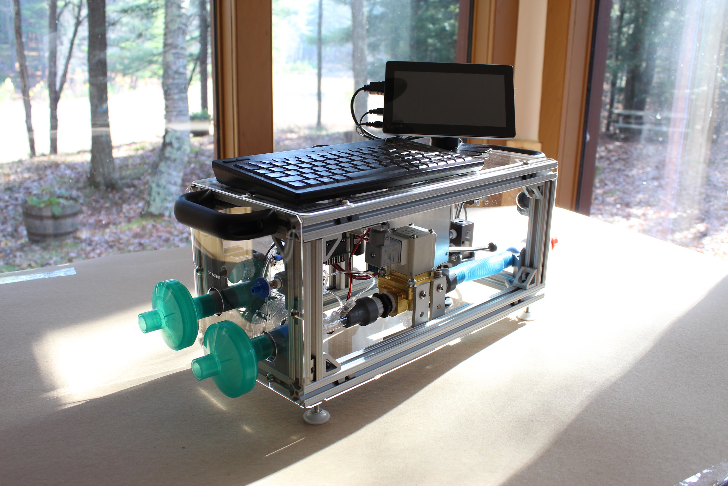
Assembly
PVP1 Assembly Instructions
This guide should help you assemble the ventilator from the parts found in the Bill of Materials:
[https://www.peoplesvent.org/en/latest/bom.html]{.underline}
We’ll first show you how to assemble the hardware, then the electronics, and finally put the two together.
The entire Solidworks Assembly, with associated part files, can be found in this Google Drive: https://drive.google.com/drive/folders/1YrJEOmOMZtXcHABYO0hEu0etJ7LAC9Lf?usp=sharing
The current assembly is named TLA_VENTILATOR_ASSY_V2.SLDASM.
Part 1. 3D Printed Components and Enclosure
1.1 3D Printing Adapters and Brackets.
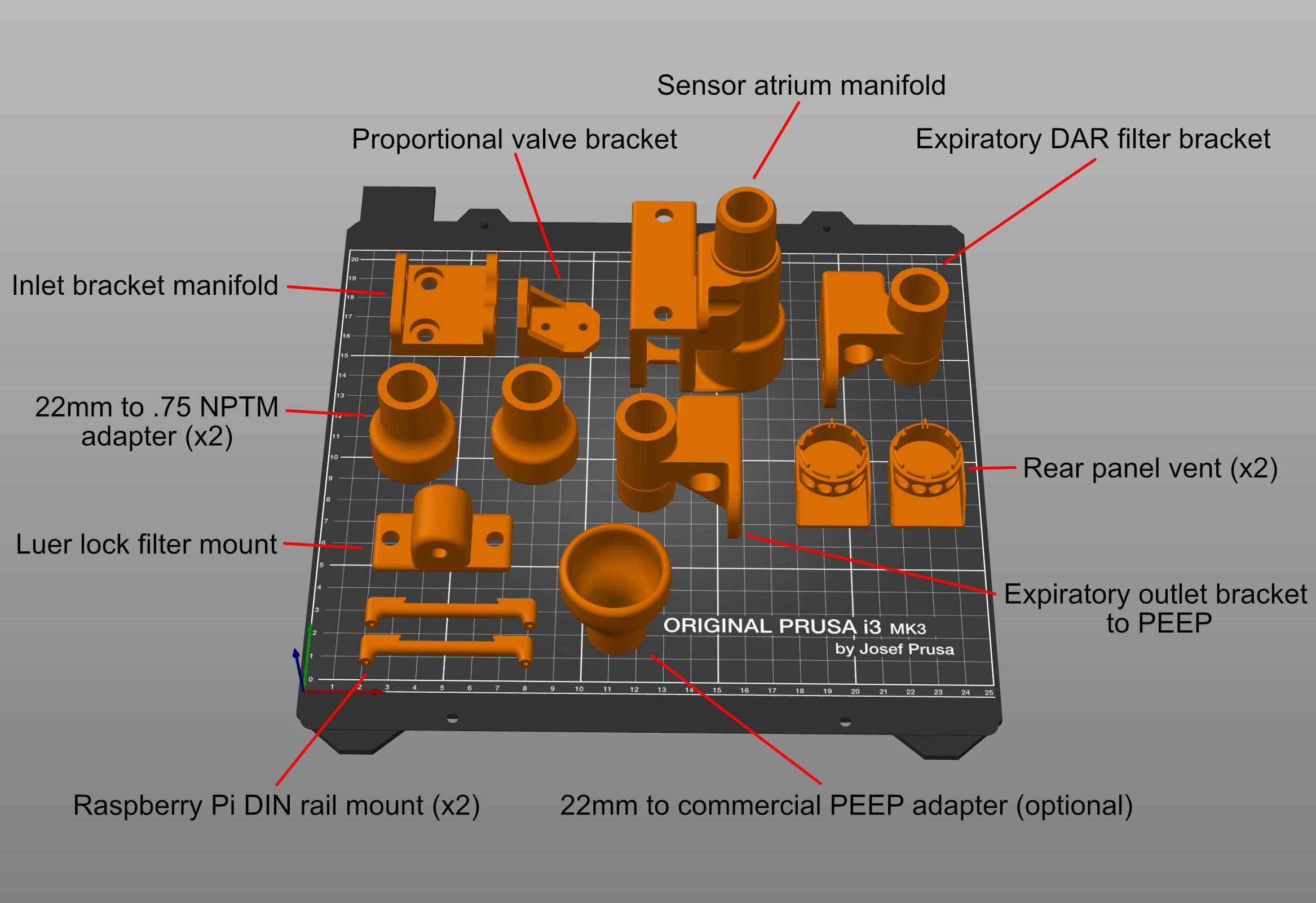
Before we can get started with assembly, you’ll need to print a few parts using a standard 3D printer. (We ran our test prints on Prusa, MakerBot, FlashForge, and Creality3D printers.)
You can download all the STL files here for printing: [https://www.peoplesvent.org/en/latest/assembly.html#d-printed-parts]{.underline}
Be sure to print airway components at as close to 100% infill as possible, and be mindful of printing orientation. An example printing setup is shown below. We do not recommend using supports or rafts unless you find them to be necessary, as they are challenging to remove. If there is a cylindrical channel, try to orient it vertically (such that the circle is traced along the build plate), which will improve circularity of the channel.
If you are using a Prusa i3, we also provide this print setup here.
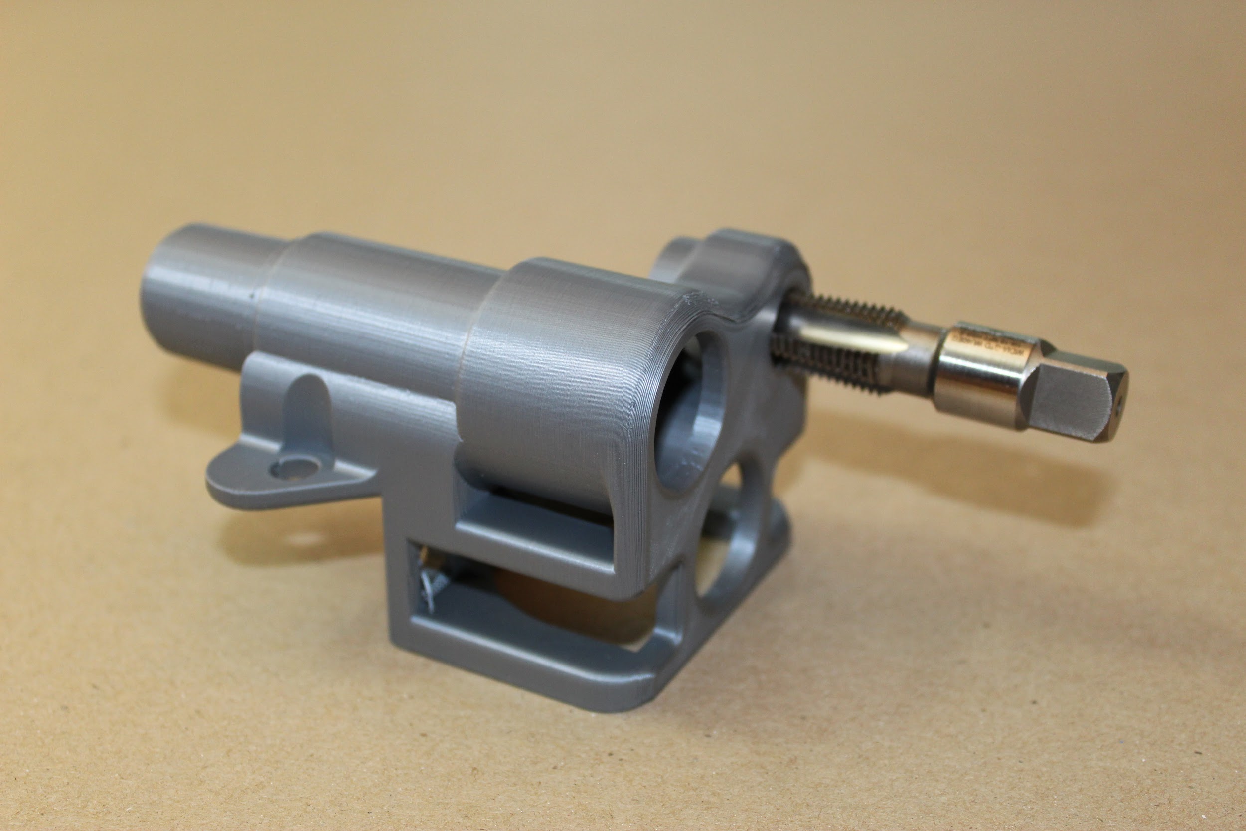
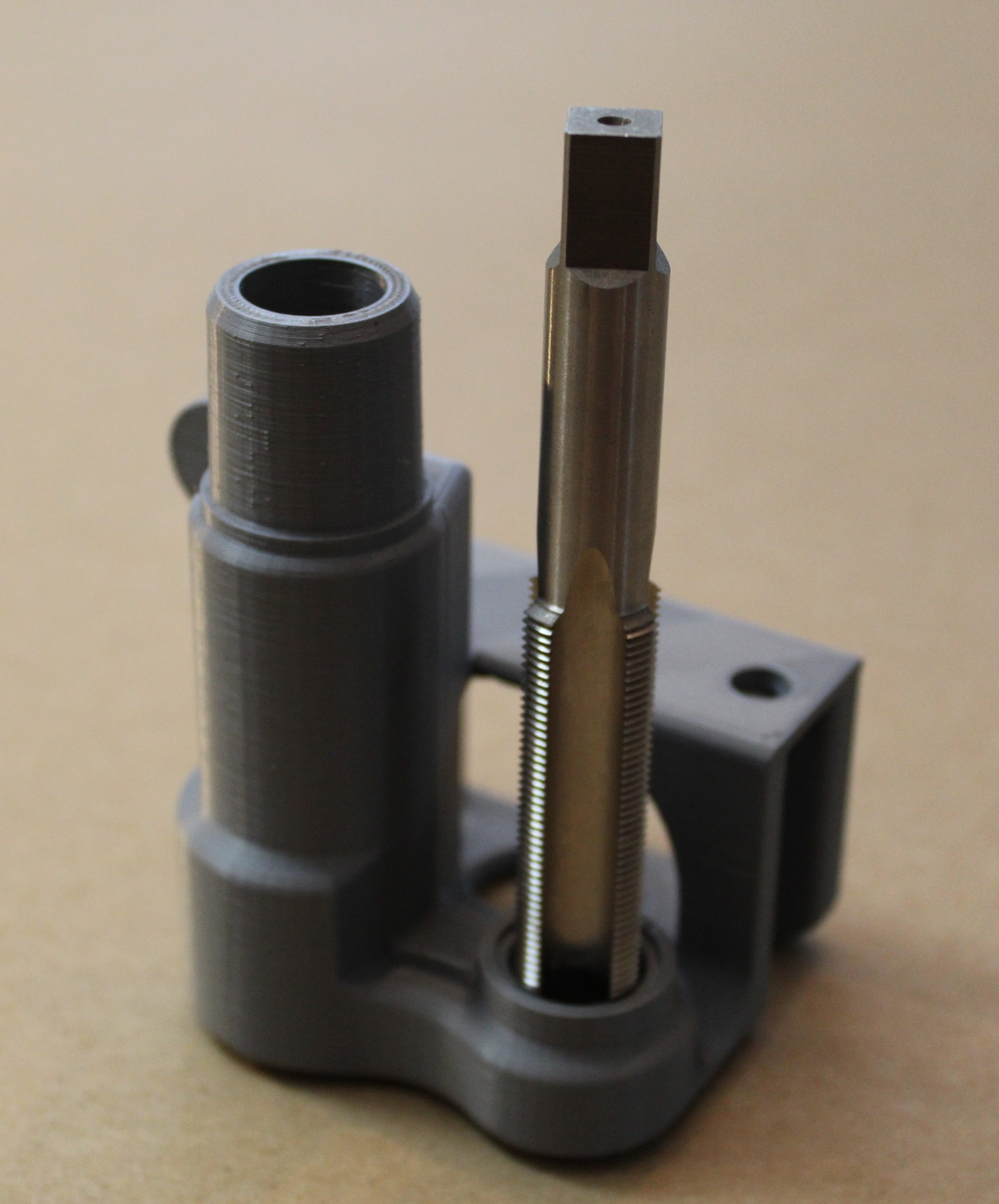
1.2 Tapping the 3D Printed Components
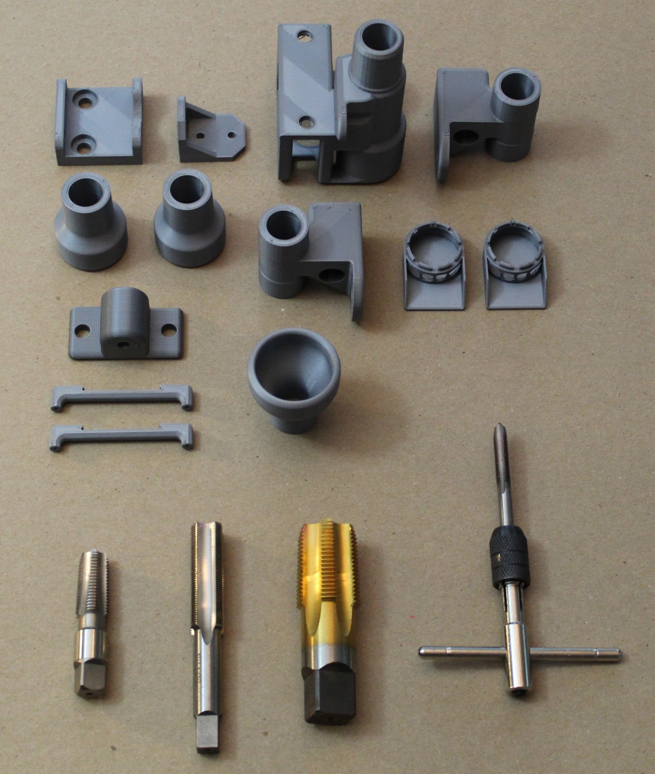
Several of the 3D printed parts will need to be tapped to enable connection with other parts in the device- such as push-to-connect adapters. You will be able to tap all of these parts by hand (since the plastic cuts easily), and the Bill of Material contains the list of taps you will need, including specialized taps such as the M16:
https://www.peoplesvent.org/en/latest/bom.html
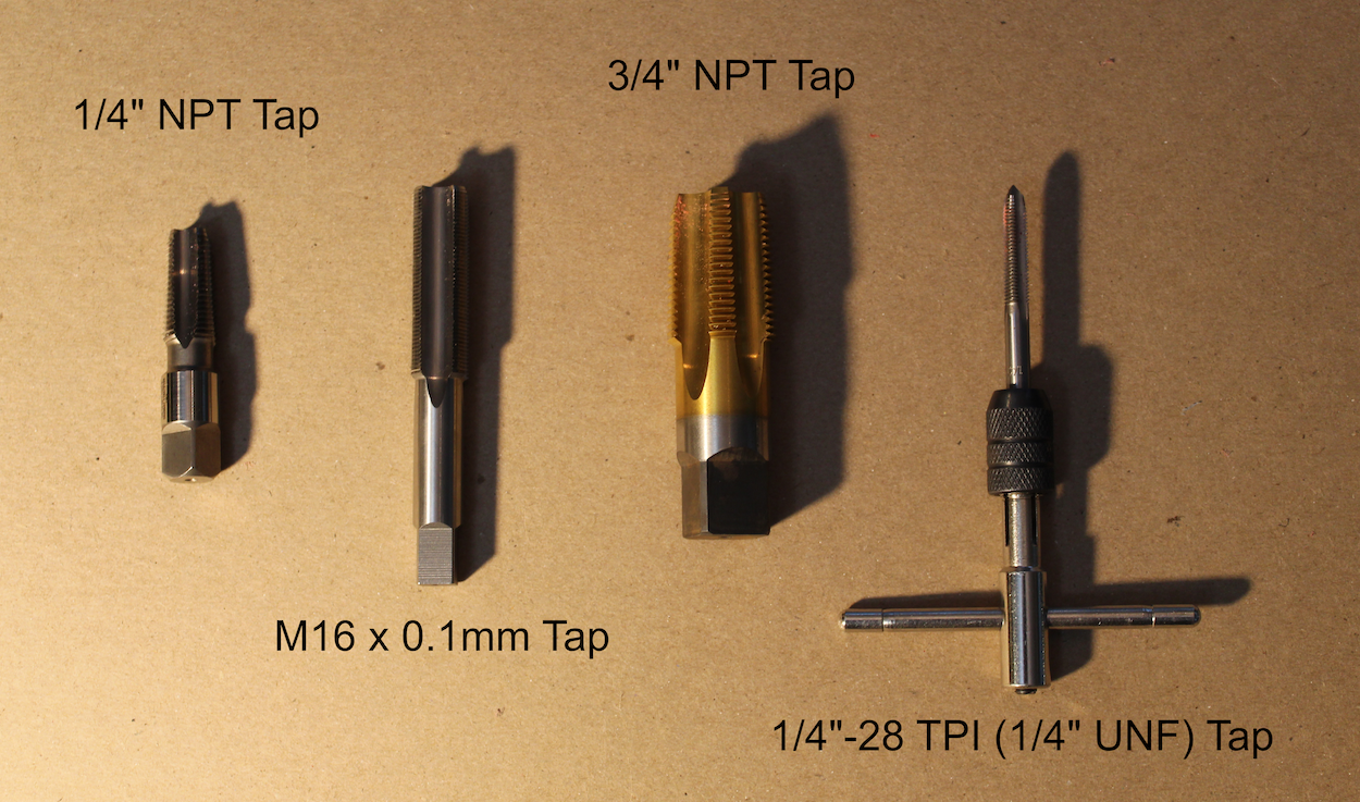
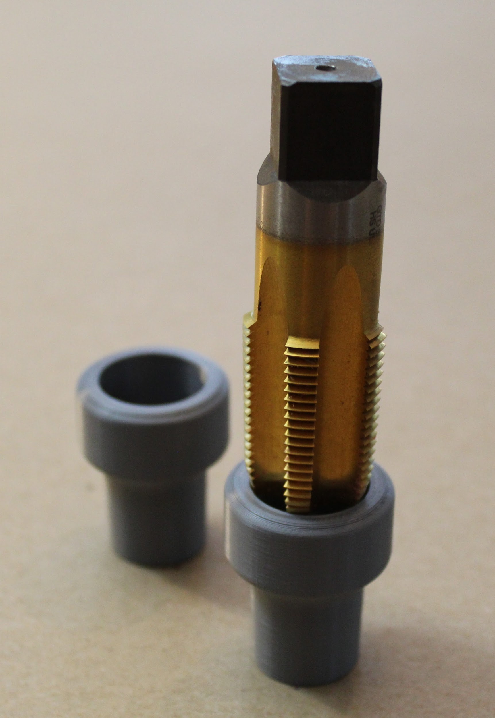
All required taps are shown below:
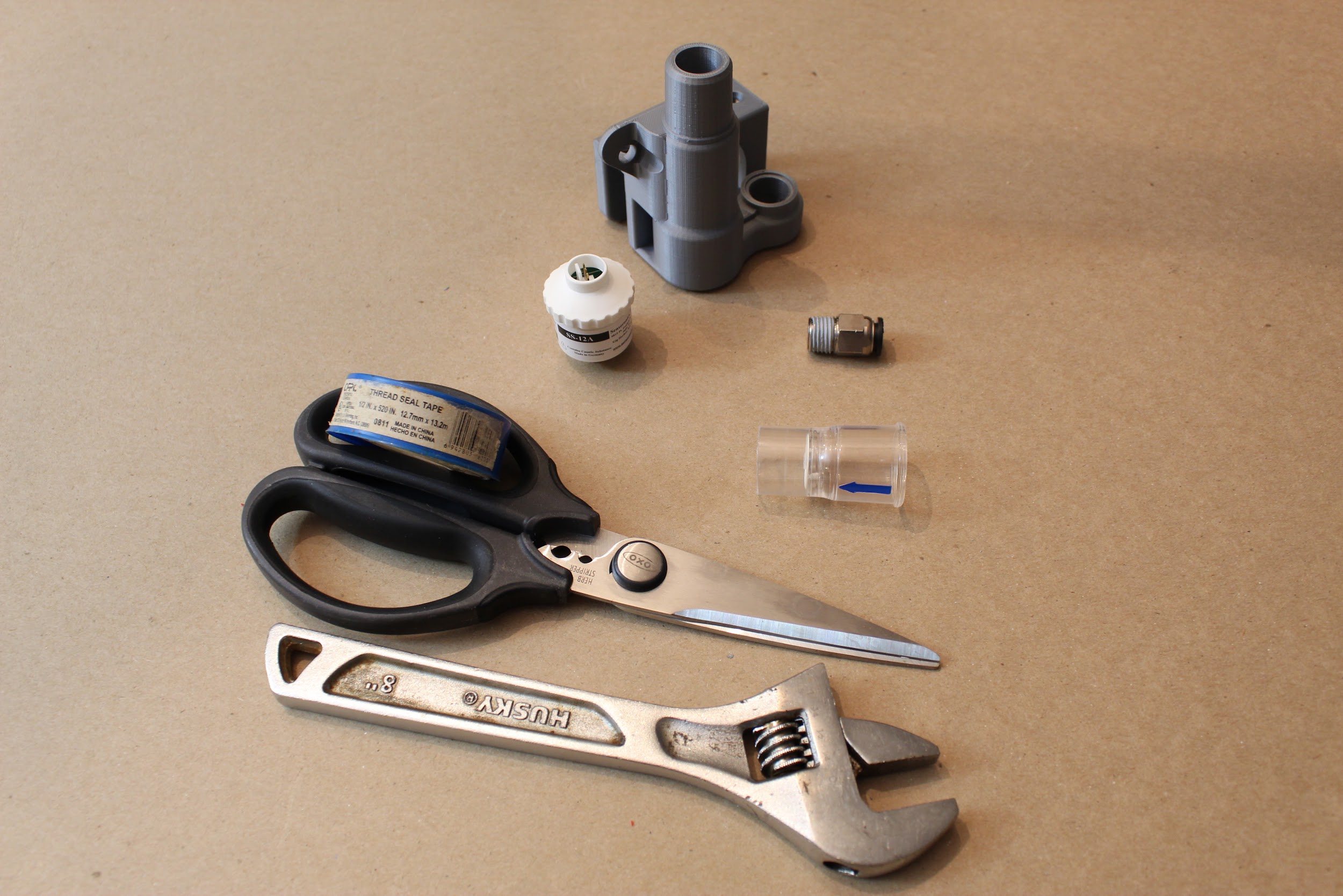
First, we will tap the Sensor Atrium component, which houses the oxygen sensor and “emergency breathing valve” check valve, and passes air from the inspiratory limb to the respiratory circuit (with a DAR filter in between).
Step 1. Use a ¼” NPT tap to thread the hole as shown below (the smaller airway hole on the flat side of the Sensor Atrium), where a push-to-connect adapter will attach.
Step 2. Use the M16 tap to thread the hole on the opposite side of the Sensor Atrium, where the oxygen sensor will attach.
Next, we will tap the adapters at either side of the expiratory solenoid.
Step 3. Use the ¾” NPT tap to thread the holes on the larger end of the two “22mm to 0.75 NPTM adapter” parts.
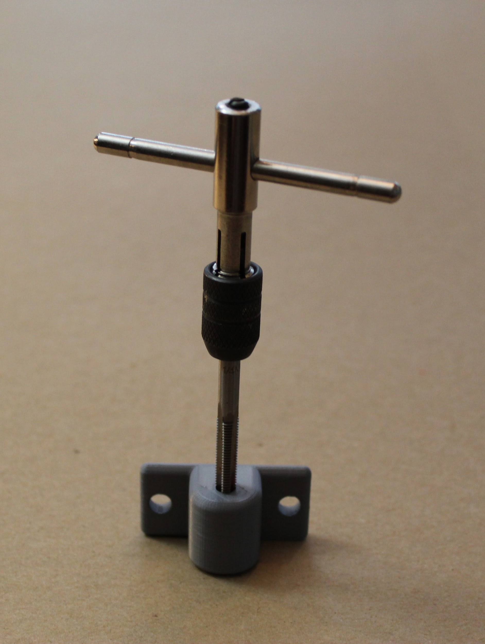
Last, we will tap the adapter to the pressure sampling lines.
Step 4. Finally, use the ¼”-28 tap to thread the two airway holes on the “Luer lock filter mount” part. These will hold the metal luer lock adapters to the gas sampling lines for monitoring pressure.
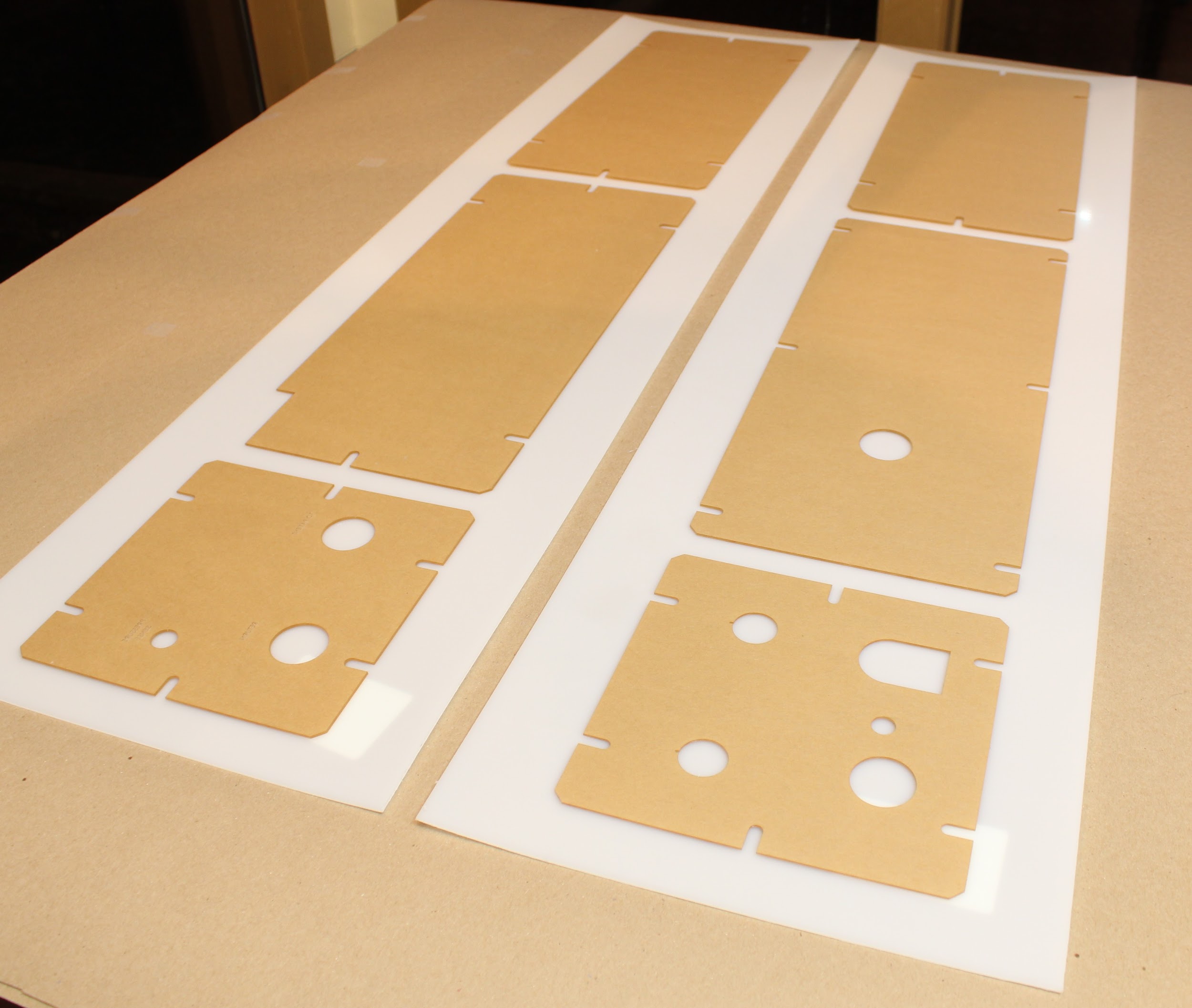
1.3 Cutting Enclosure Pieces.
Step 1. Laser cut, or cut out by hand, the six HPDE side panels.
Cut all panels out of the 1/16” HPDE sheets. If you wish to cut these pieces using a laser cutter, we provide DXF files here, under “Enclosure”: [https://www.peoplesvent.org/en/latest/assembly.html]{.underline}
Cuts can also be made by hand using a sharp pair of scissors and a razor-cutter. Pieces are 17 ⅞” by 7 ⅞” (45.4025 cm by 20.0025 cm), or 7 ⅞” by 7 ⅞” (20.0025 cm by 20.0025 cm) along the outer dimensions. Inner hole placement can be determined from the documentation, also at:
[https://www.peoplesvent.org/en/latest/assembly.html]{.underline}
(We cut our side panels for the demo out of acrylic for ease of visibility.)
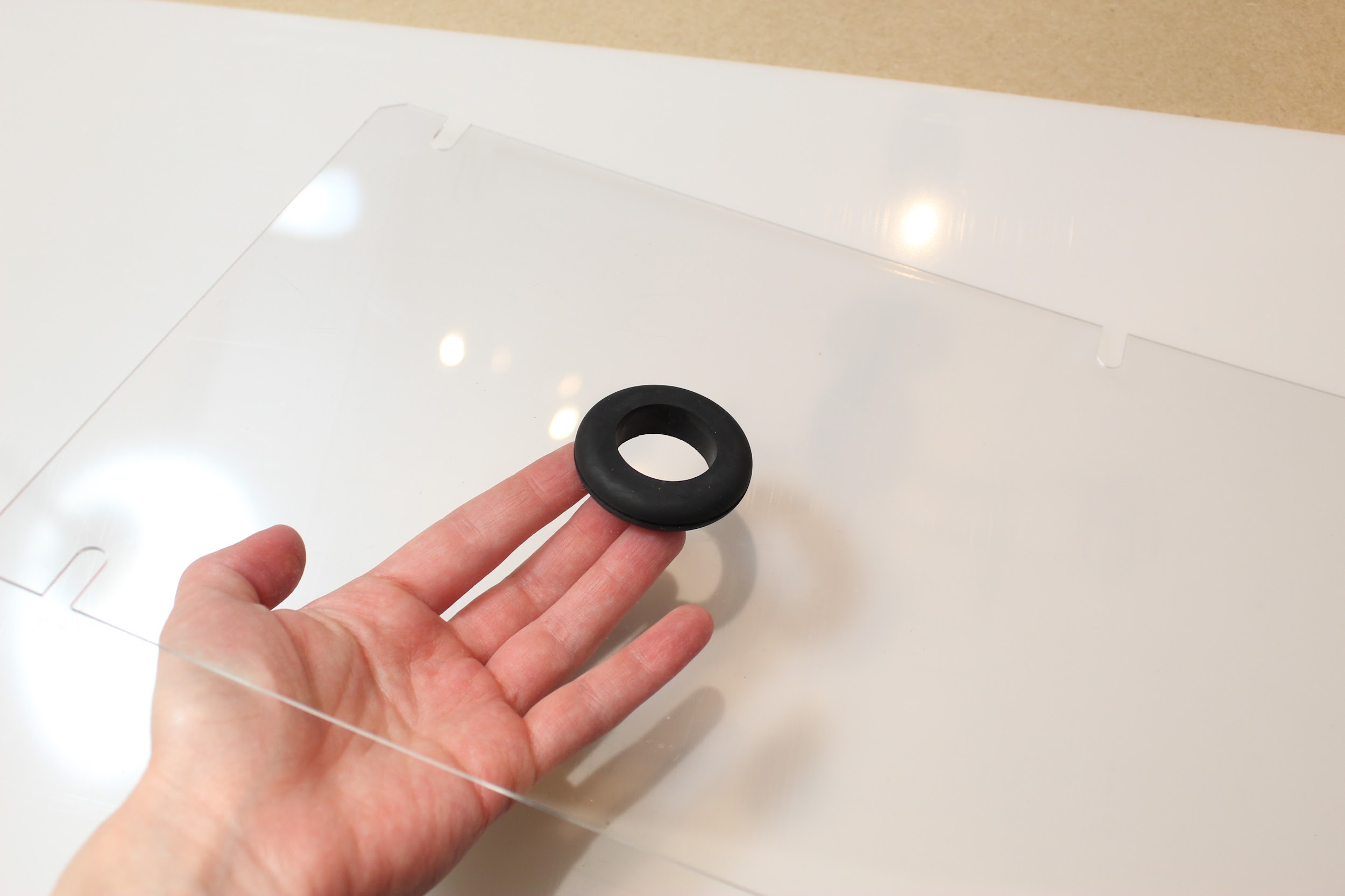
Step 2. Insert the rubber grommet(s).
The bottom panel includes a hole for a large rubber grommet. Insert this by hand.
If you wish, you may also insert a small custom grommet in the back panel.
Part 2. Basic Hardware Assembly
2.1 Assembling the bottom frame
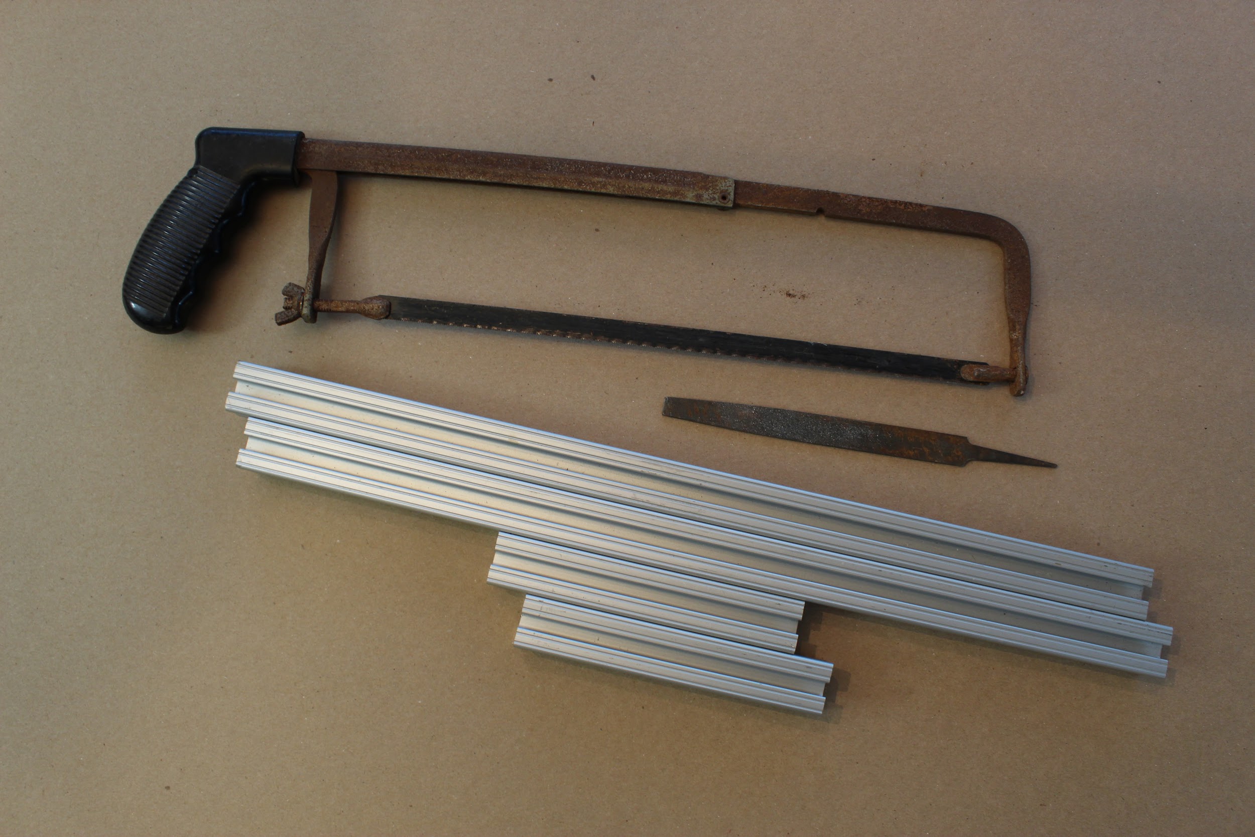
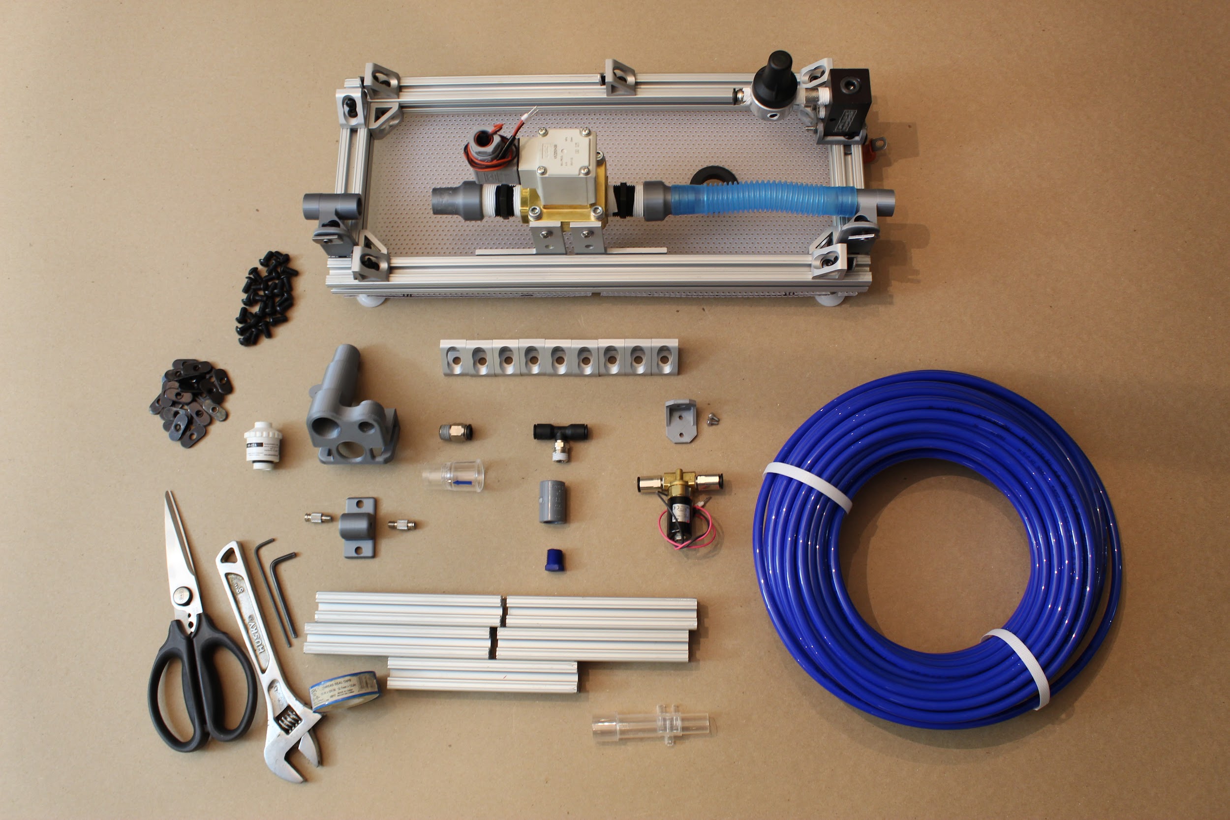
Step 1. Cut the 80/20 (“T-slotted framing”) to appropriately sized pieces: In total, you will need 4 pieces of length 17 ⅞ in (45.4025 cm), and 9 pieces of length 5 ⅞ in (14.9225 cm).
You can cut the aluminum 80/20 pieces by hand with a hack-saw, or using machinery such as a bandsaw. Either way, be sure to file down any rough edges afterward!
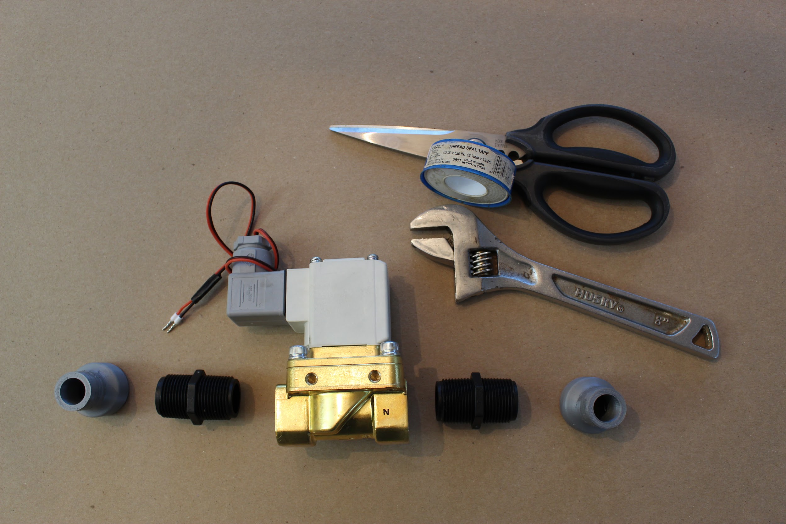
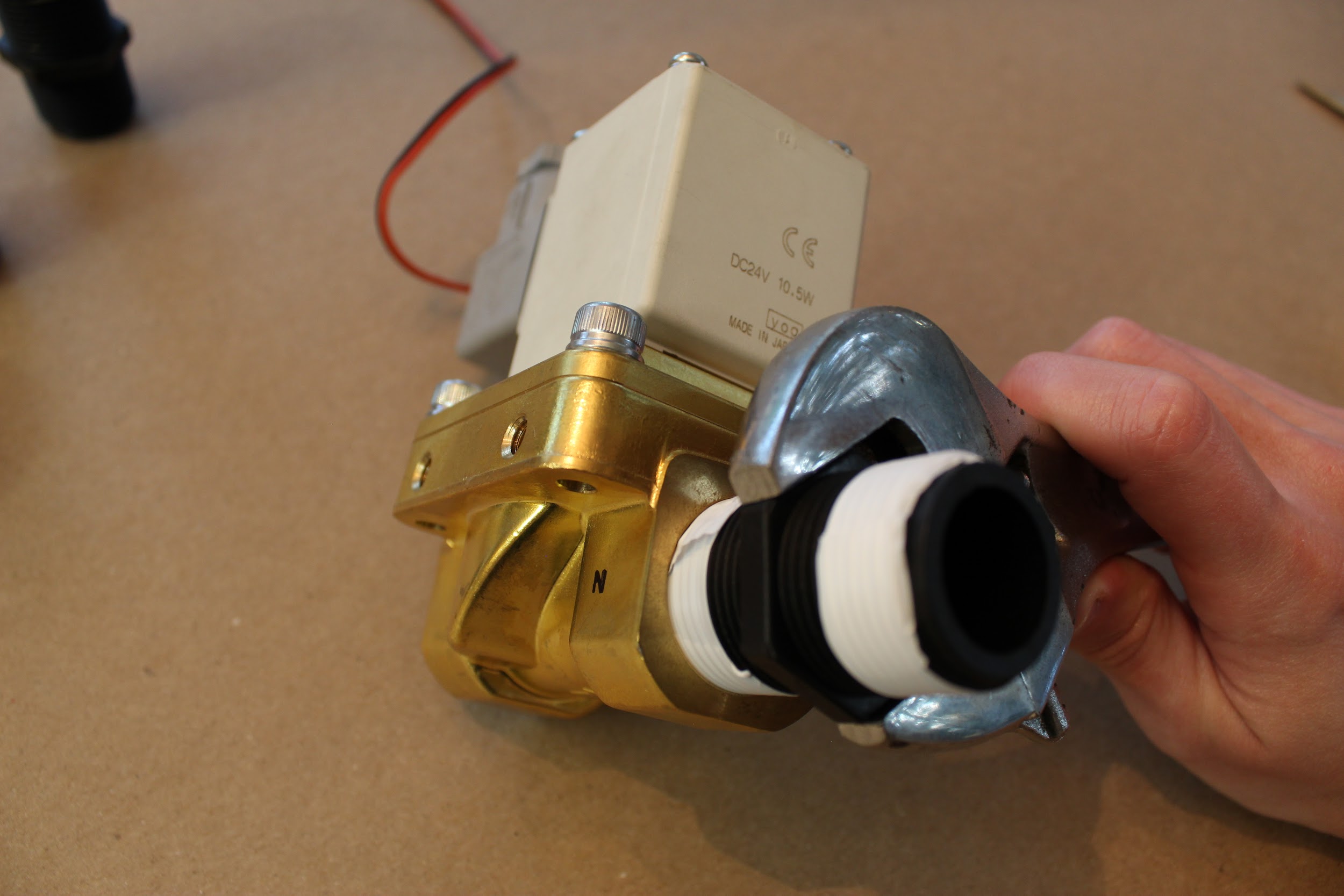
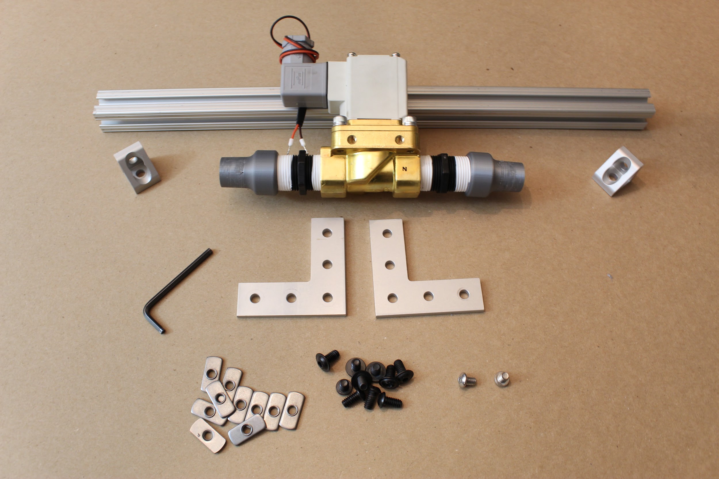
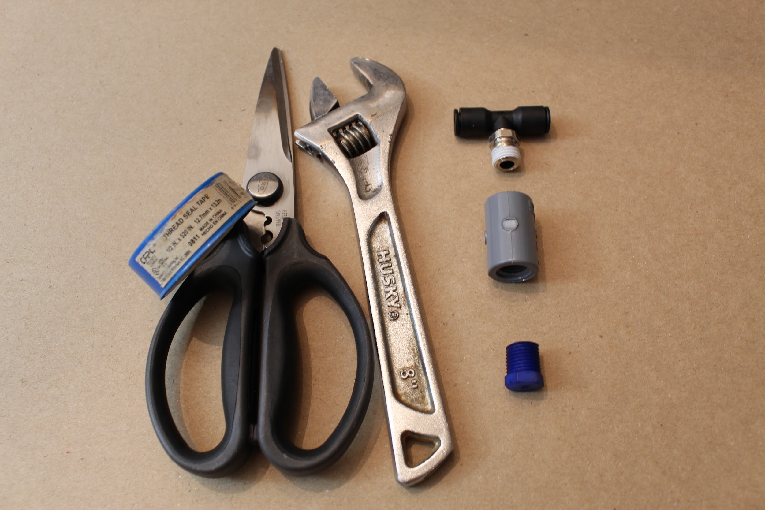
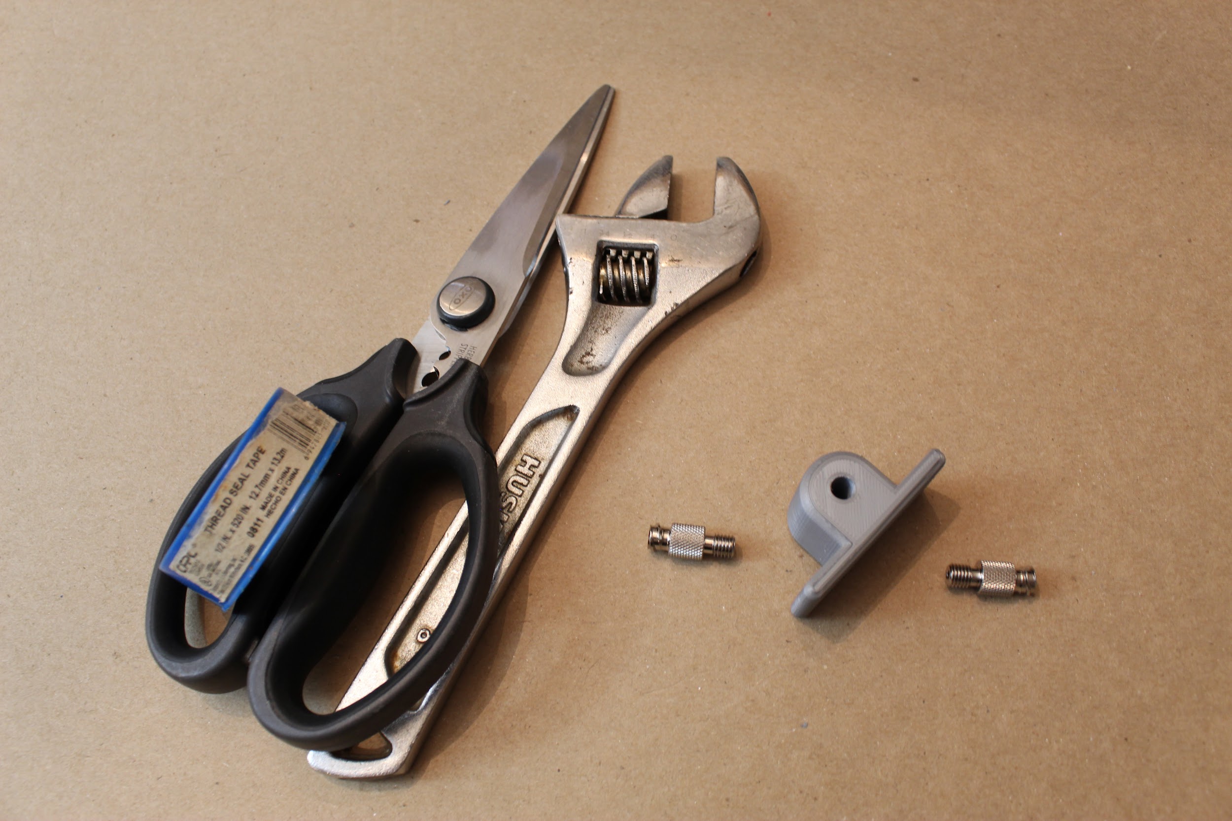
Step 2. Attach the ¾” NPT (male-male) connectors to either side of the expiratory solenoid, and then attach the two “22mm to .75 NPTM adapter” parts to those, as shown. When attaching any airway threaded parts in this assembly process, be sure to use PTFE thread sealant tape, wrapping twice around the threads, in the direction shown (away from your body if the threads are oriented towards the right).
(Note: From now on, we will not explicitly write out the need for Teflon tape; be sure to use it whenever a threaded airway component is involved!)
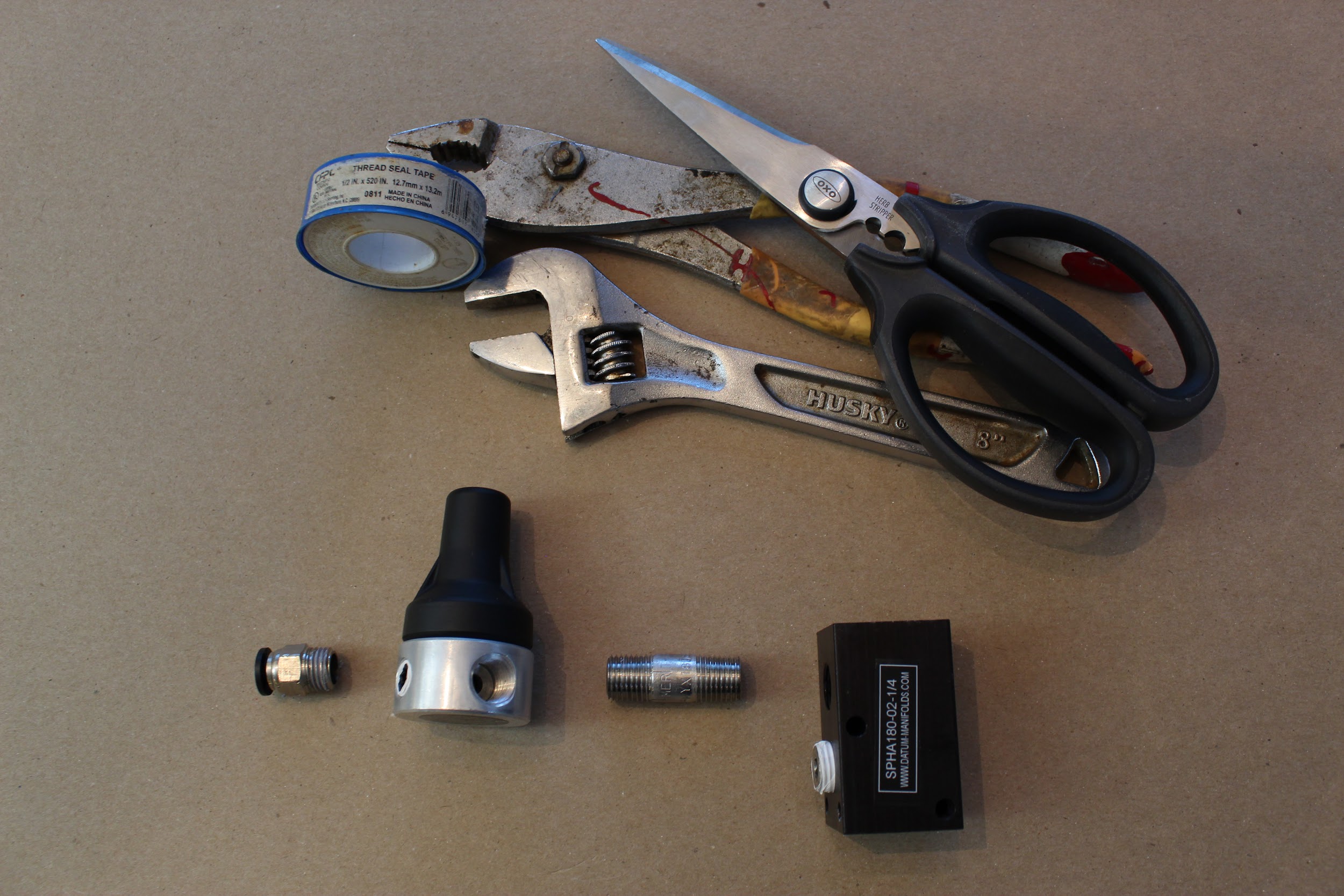
Step 3. Ensure that the two side ports of the pressure regulator are blocked off, with the plugs included with the part (and Teflon tape, as always). Attach a ¼” NPT push-to-connect adapter to the pressure regulator on the “outlet” side: check the bottom of the part to determine which side is “IN” for “inlet”. The inlet manifold will have two ¼” NPT ports on the same side: plug one of those with the manifold plug, and attach the other end to the ¼” NPT connector. Attach the other end of this connector to the “inlet” end of the pressure regulator.
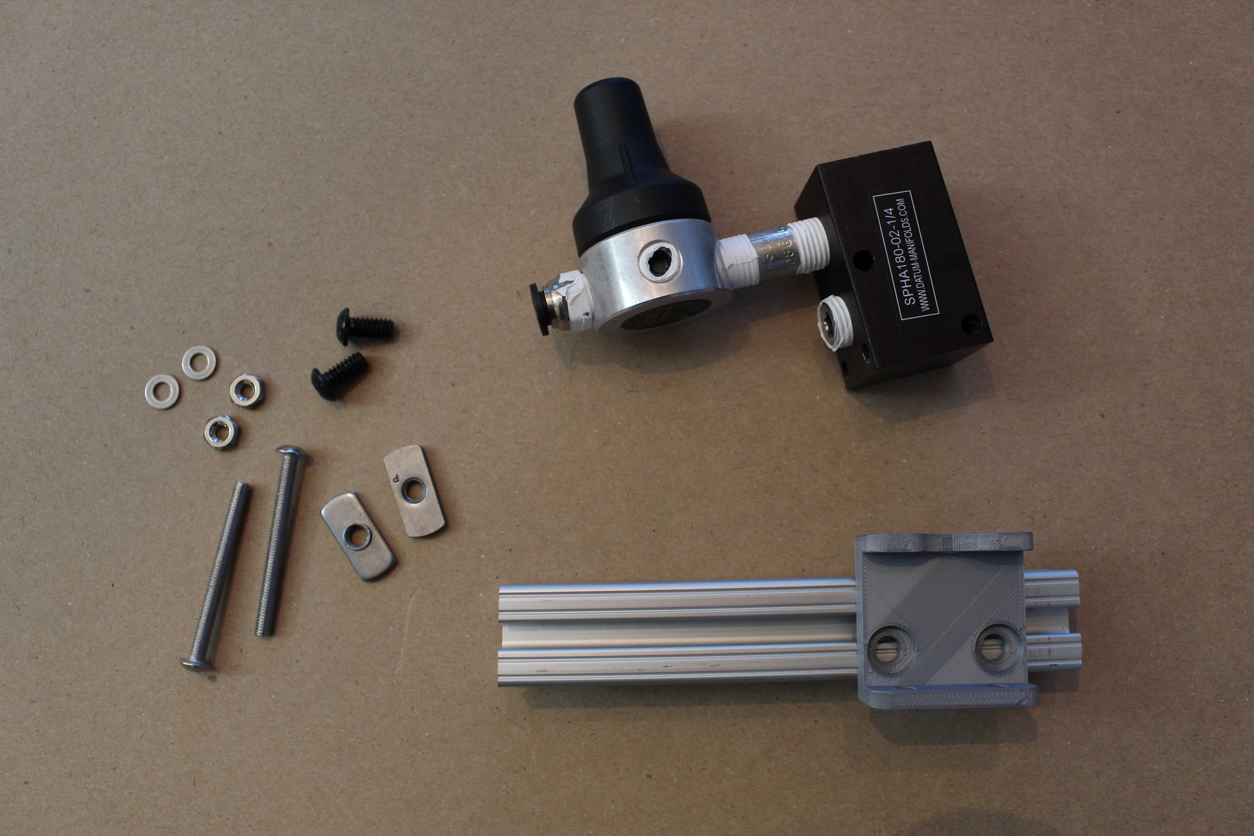
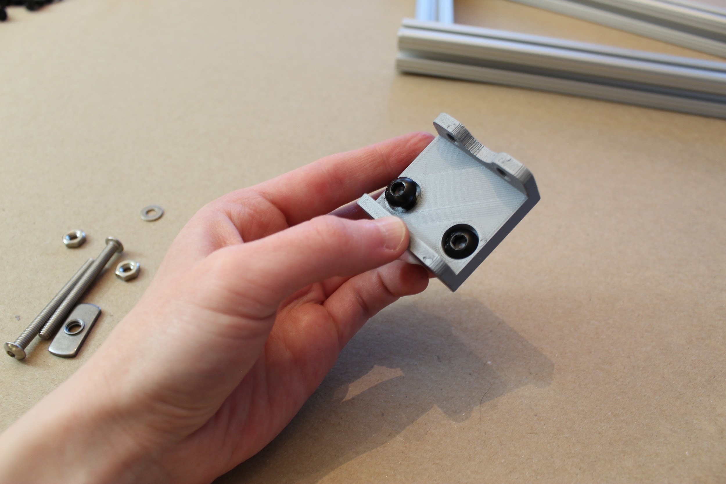
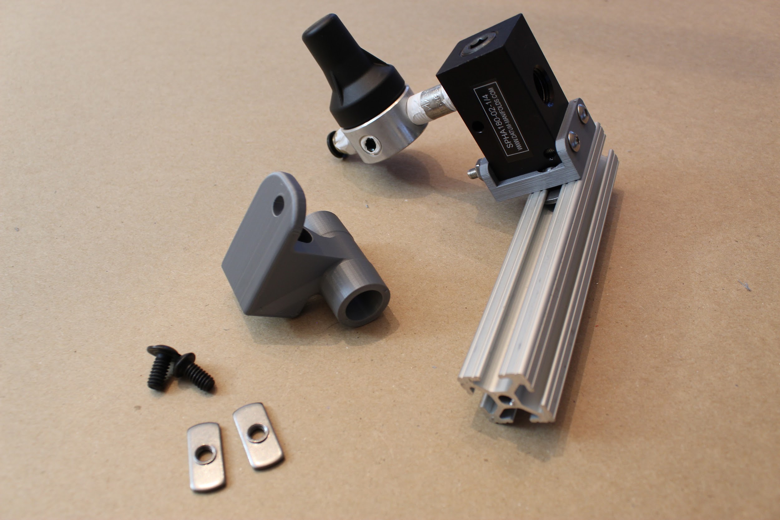
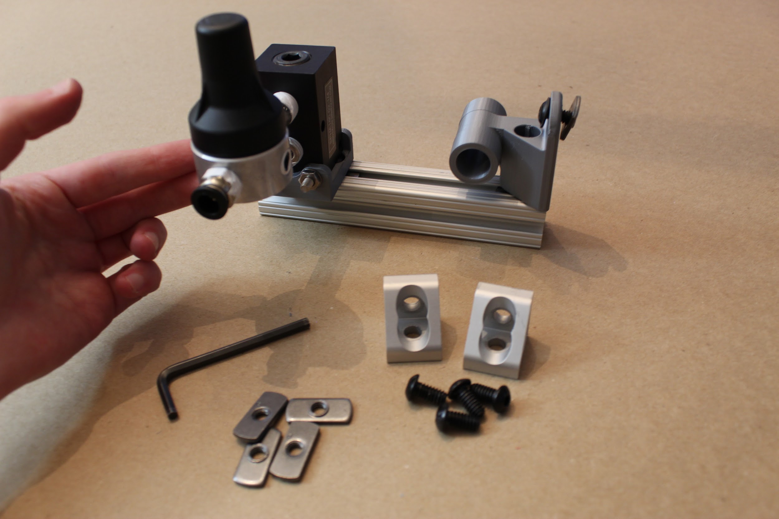
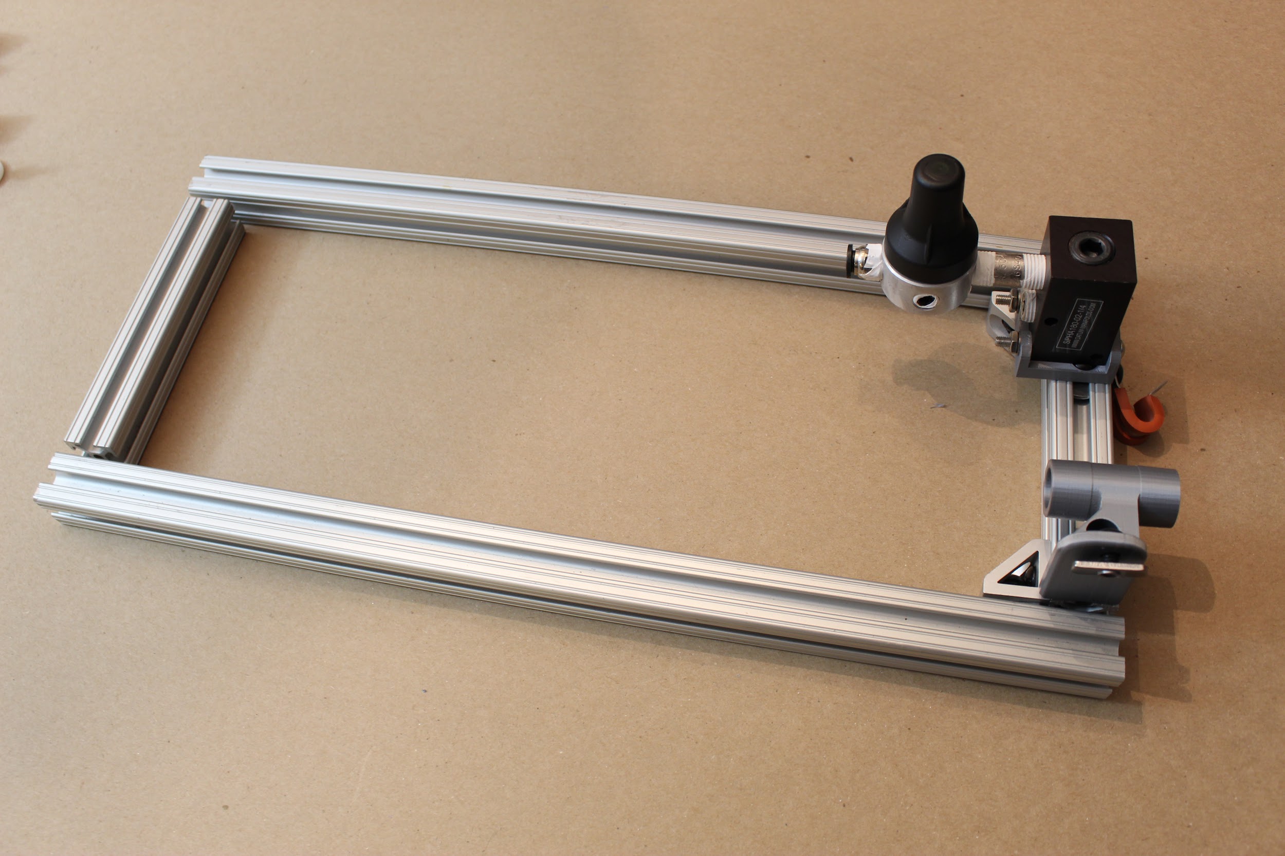
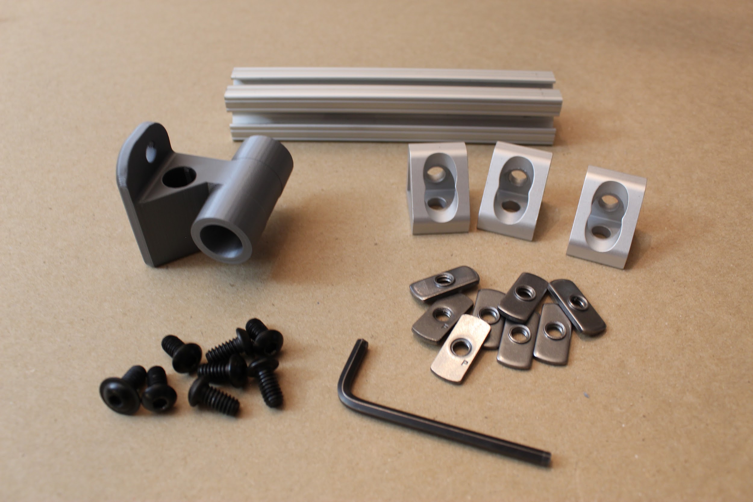
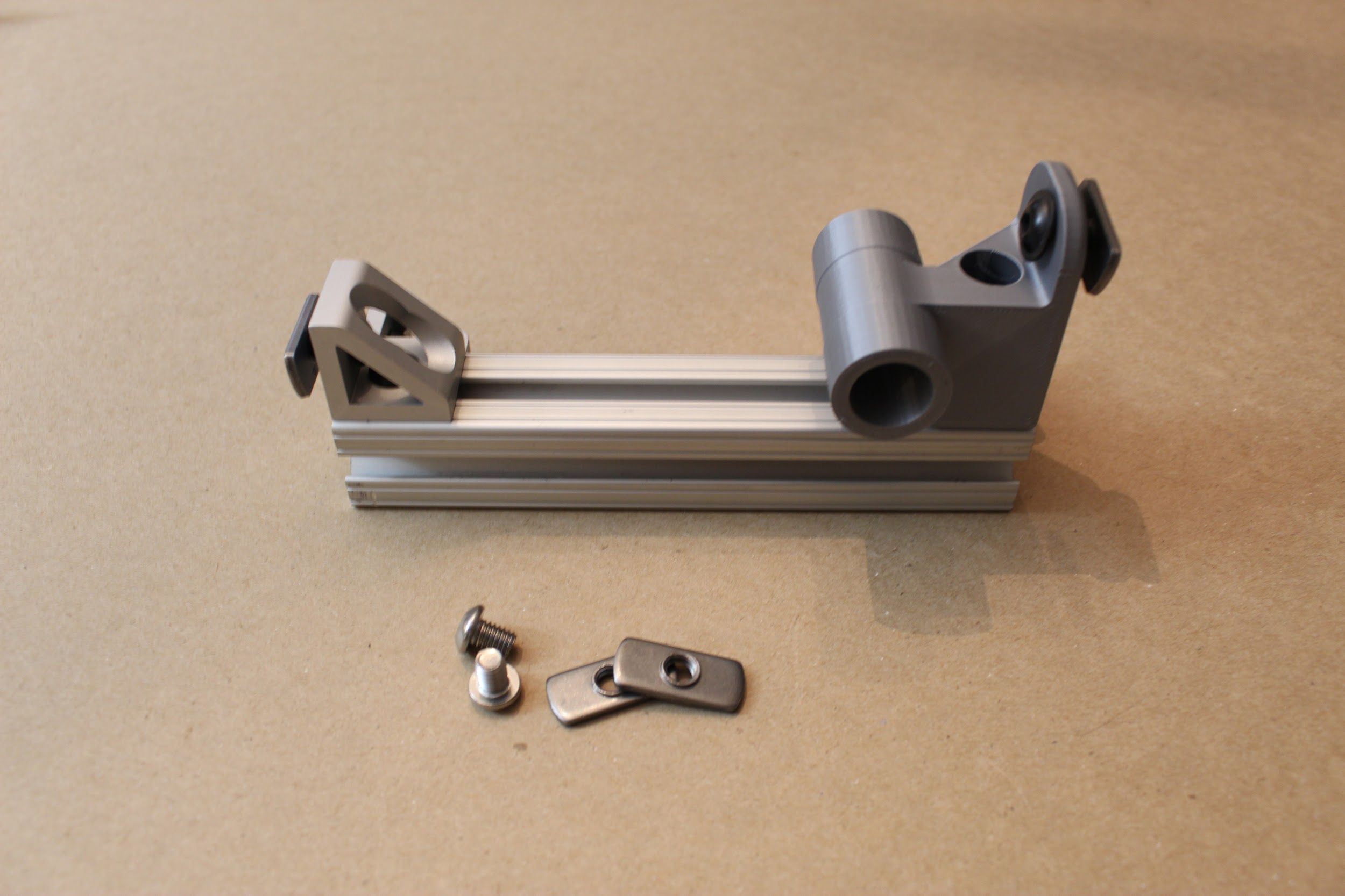
Step 4. Mounting the inlet manifold.
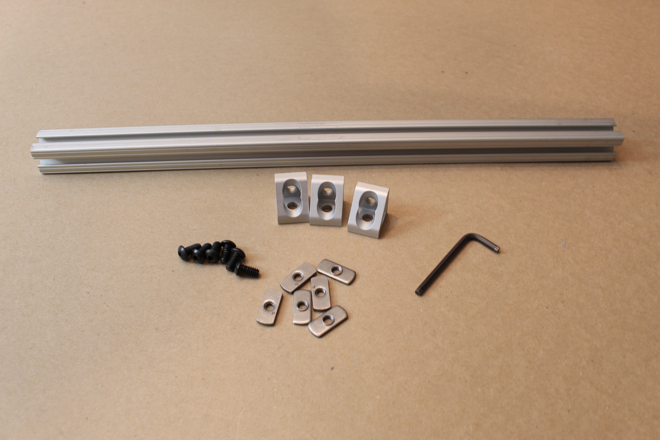
First, attach the 3D-printed “Inlet manifold bracket”, by pushing two standard button-head screws down from the top of the piece (as shown, such that the button heads fall in the grooves), then loosely attaching a hex nut to each. Then, slide the two hex nuts into a T-slot of a short (5 ⅞”) 80/20 piece, and use an Allen key to secure the screws such that the printed piece is as far to the “right” as it can go (as shown), without the hex nuts extended past the length of 80/20.
Tip: when attaching hex nuts, make sure the side with the nub is facing down (such that it touches the inner channel of the 80/20 T-slot).
Then, insert the inlet manifold into the printed piece, as shown: if the printed part is to the right of the 80/20 length, then the pressure regulator should be oriented away from you. Insert the 2” button head hex drive screws through the remaining holes in the 3D printed piece, to secure the inlet manifold, as shown (also away from you). Finally, attach a washer (W_10_NARROW_0.406OD_316_SS) and hex nut (LN_10-32_STAINLESS_18-8) to each.
Step 5. Attach the “Expiratory outlet bracket to PEEP”.
Drop one standard button head hex screw down the deeper channel, and attach as before: loosely screw on a hex nut, slide it in the channel, and then use an Allen key to tighten the screw. This time, tighten the hex screw such that the printed part is in-line with the edge of the 80/20 piece, as shown. Then, insert a second button head hex screw, facing outward as shown, and loosely attach a hex nut (you will tighten this later).
Step 6. Attach corner brackets to finish this frame piece.
Pre-assemble the gusset (corner) brackets by inserting a hex screw into each hole, and then loosely attaching a hex nut to each, as shown. Tighten the gussets so that they align with the edge of the 80/20 piece, as shown, keeping the second hex nut on each piece loose. (You will use these to attach another 80/20 piece later.)
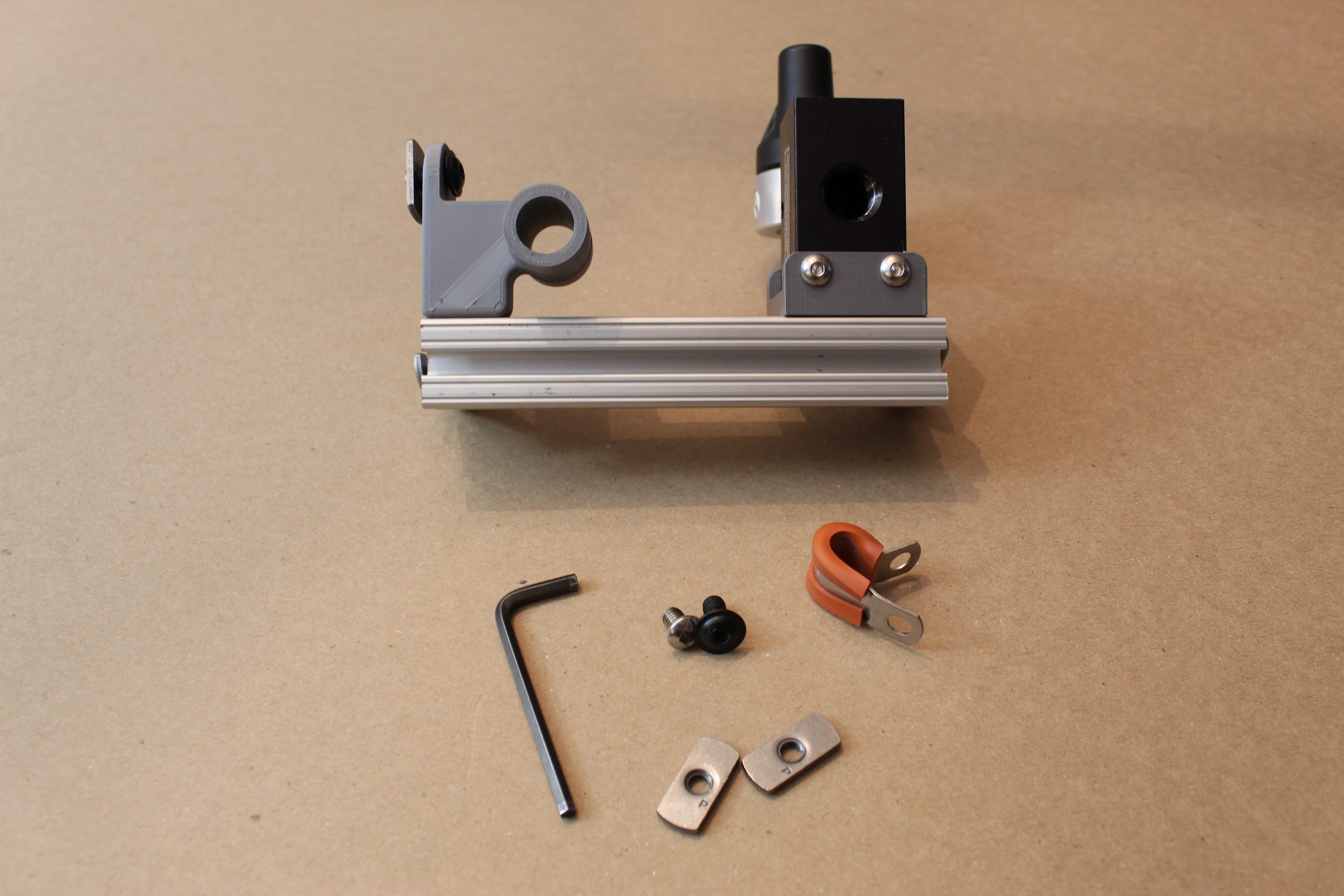
Step 7. Attach cable tie and side panel screw.
If you intend to use the cable P-clip for cable management, and to attach the HPDE side panels, attach the P-clip using a standard button head hex screw, and mount an additional hex screw for attaching the side panel later.
Progress: One piece of the bottom frame is assembled!
Step 8. Assemble the opposite side of the frame.
Assemble a second short (5 ⅞”) piece of 80/20 as shown: this uses the 3D printed part called the “Expiratory DAR filter bracket”, which will mirror the “Expiratory outlet bracket to PEEP” part on the opposing frame leg. Also, attach three gusset (corner) brackets, as shown.
*Note: if you intend to attach the side panels, leave off the corner bracket on the same side as the 3D printed piece. If you’re not using the side panels, keep the bracket here for additional support!
Step 9. Attach side panel screws.
As before, if you plan to attach HDPE side panels later on, attach the screws for them now, as shown.
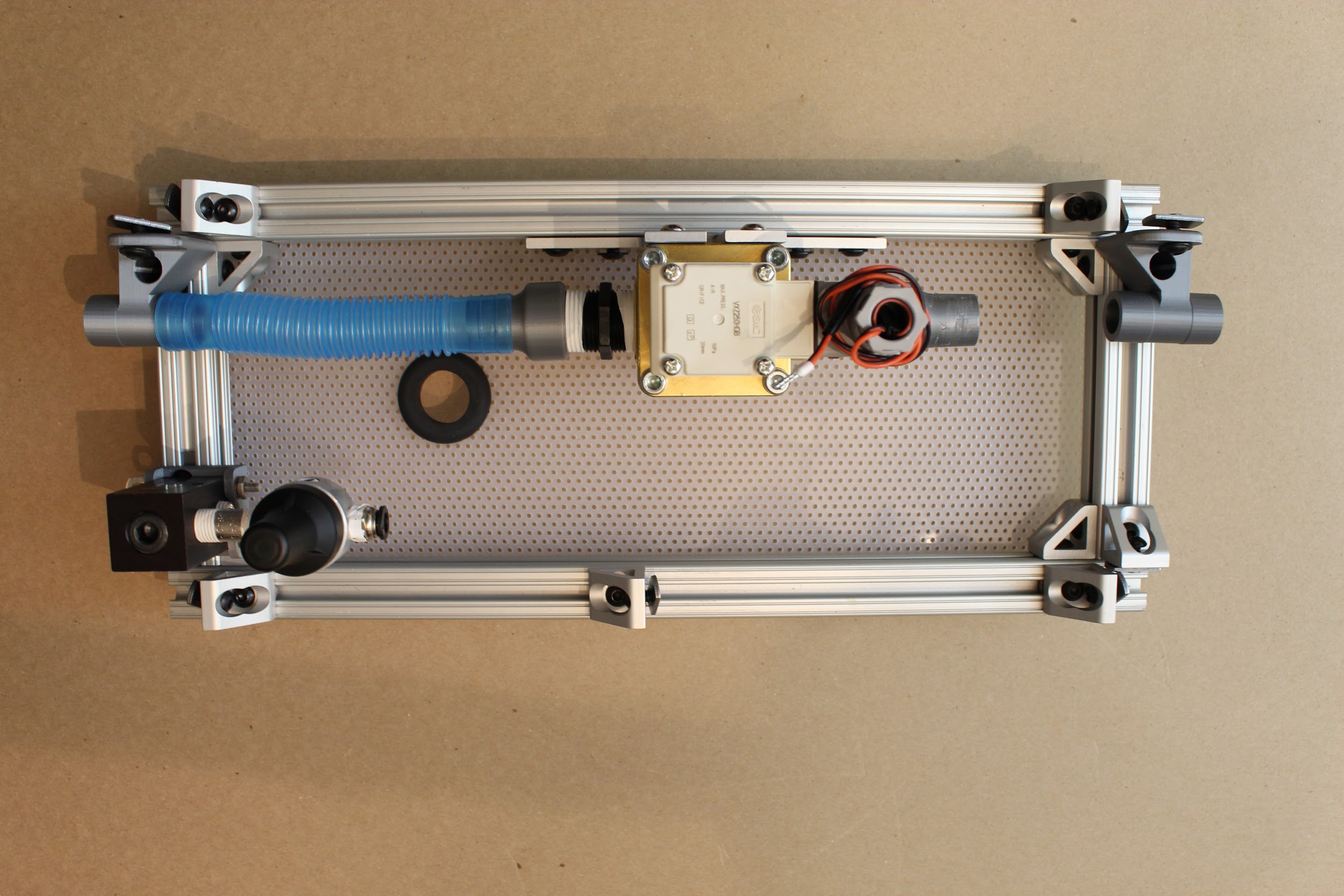
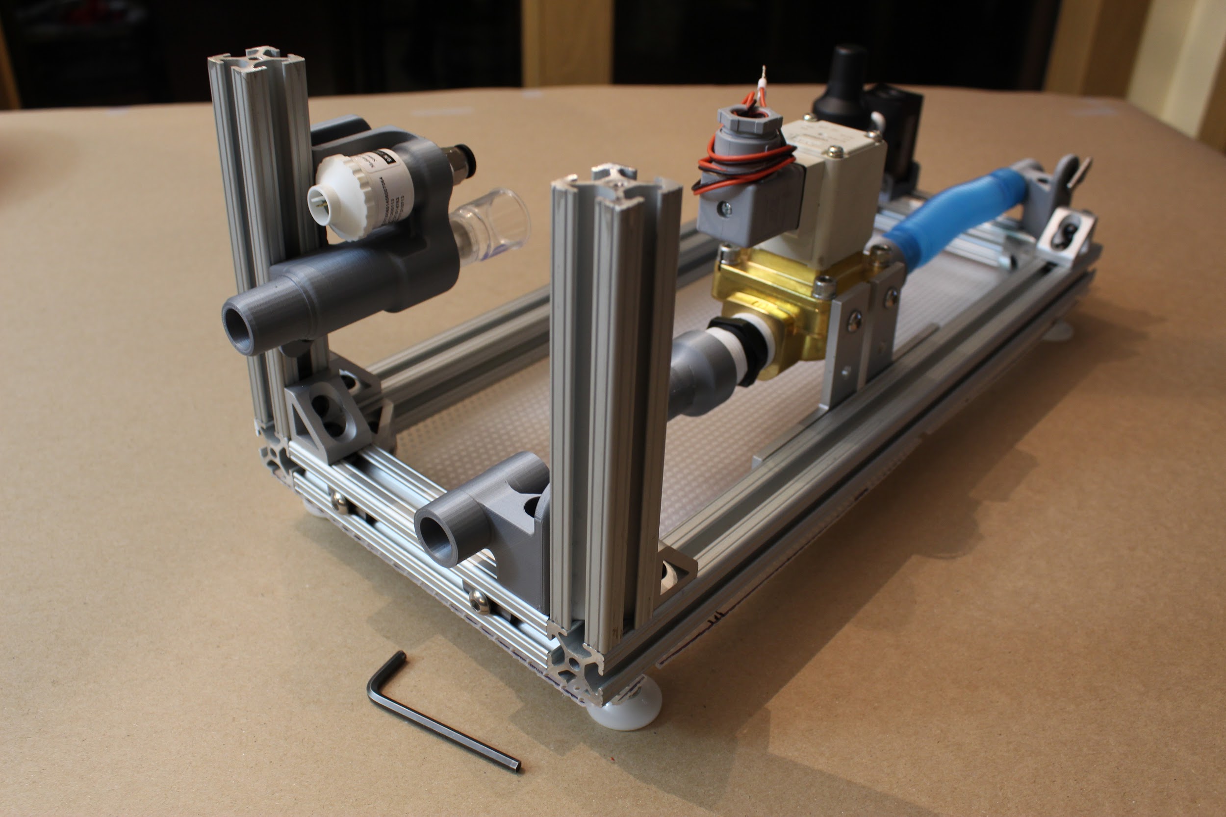
Step 10. Attach the expiratory solenoid assembly to the frame.
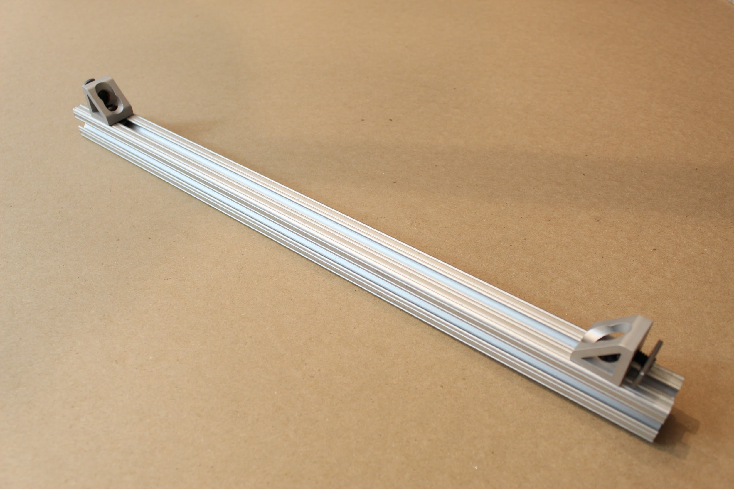
First, assemble and attach two gusset (corner) brackets to their hex
screws/nuts, then affix to a long (17 ⅞”) leg of the framing, leaving 1” from the end of the piece on each side (that is, leaving space for a vertical piece of 80/20).
Then, attach three hex screws/nuts to the lower rows of each
90-degree angle bracket as shown; then attach the angle brackets by inserting a short (1mm long) button head screw through the topmost hole of each angle bracket in the opposite direction. These shorter hex screws will screw directly into the solenoid.
Finally, slide the hex nuts attached to the angle brackets into the
T-slot of the 80/20 piece, such that the gusset brackets and solenoid are oriented above the 80/20 piece, as shown. Loosely tighten these in place; you will adjust the position of the solenoid later.
Step 11. Attach gusset (corner) brackets to the opposing 80/20 leg.
Assemble the gusset (corner) brackets with hex screw/nuts as before, and attach them to a long (17 ⅞”) 80/20 piece. Leave 1” of space from each of the side gussets (sufficient space for a vertical 80/20 piece), and affix the third bracket just off-center (to support a centered, vertical 80/20 piece).
Step 12. Assemble the bottom frame components.
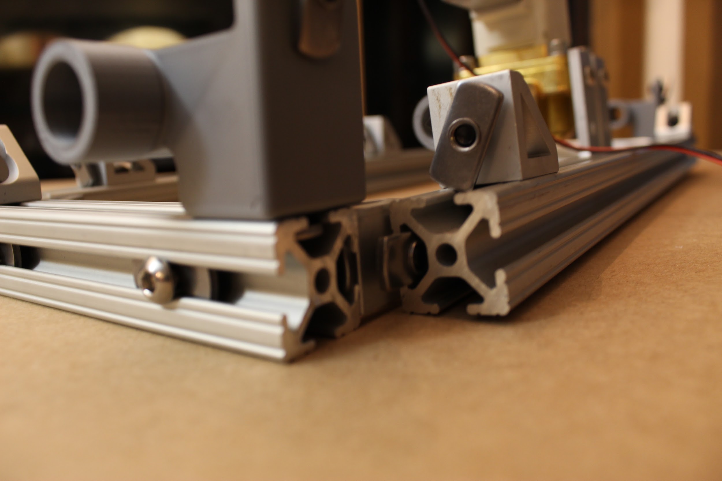
Slide the hex nuts on the shorter 80/20 pieces you have assembled into the longer 80/20 slots, and use an Allen key to tighten the screws in place, as shown. The shorter 80/20 legs should be flush with the ends of the longer 80/20 legs when you are done, and the gusset (corner) brackets will help stabilize the frame.
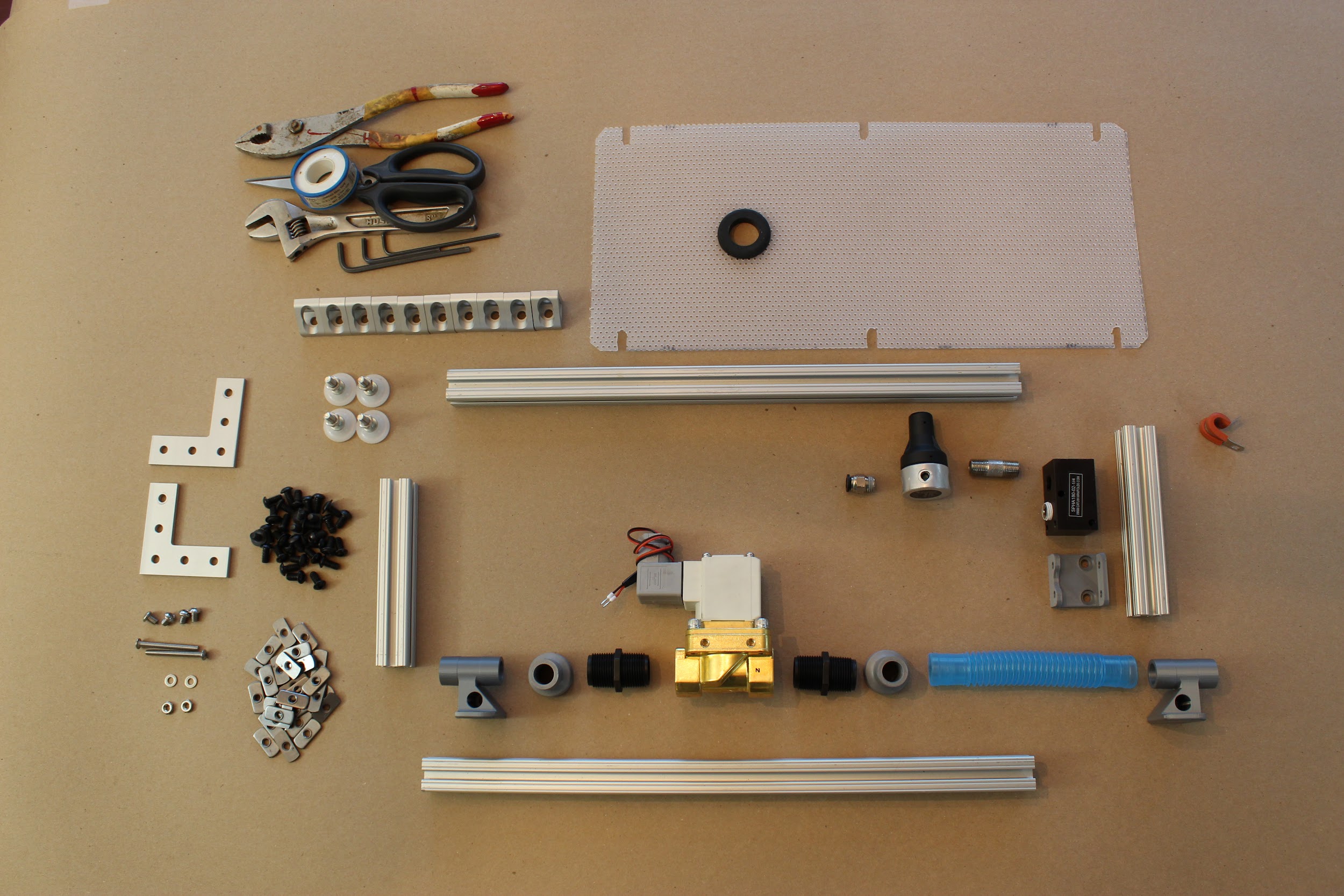
Step 13. Attaching the ventilator “feet” and bottom panel.
If you are attaching the lower, perforated HPDE sheet, insert the rubber grommet. Pre-assemble the shorter (1mm) button head screws to hex nuts, and the leveling mounts (feet) to hex nuts. Use these to attach the lower HPDE panel as shown, by sliding the hex nuts along the long channels on the bottom of the frame assembly; then tighten in place.
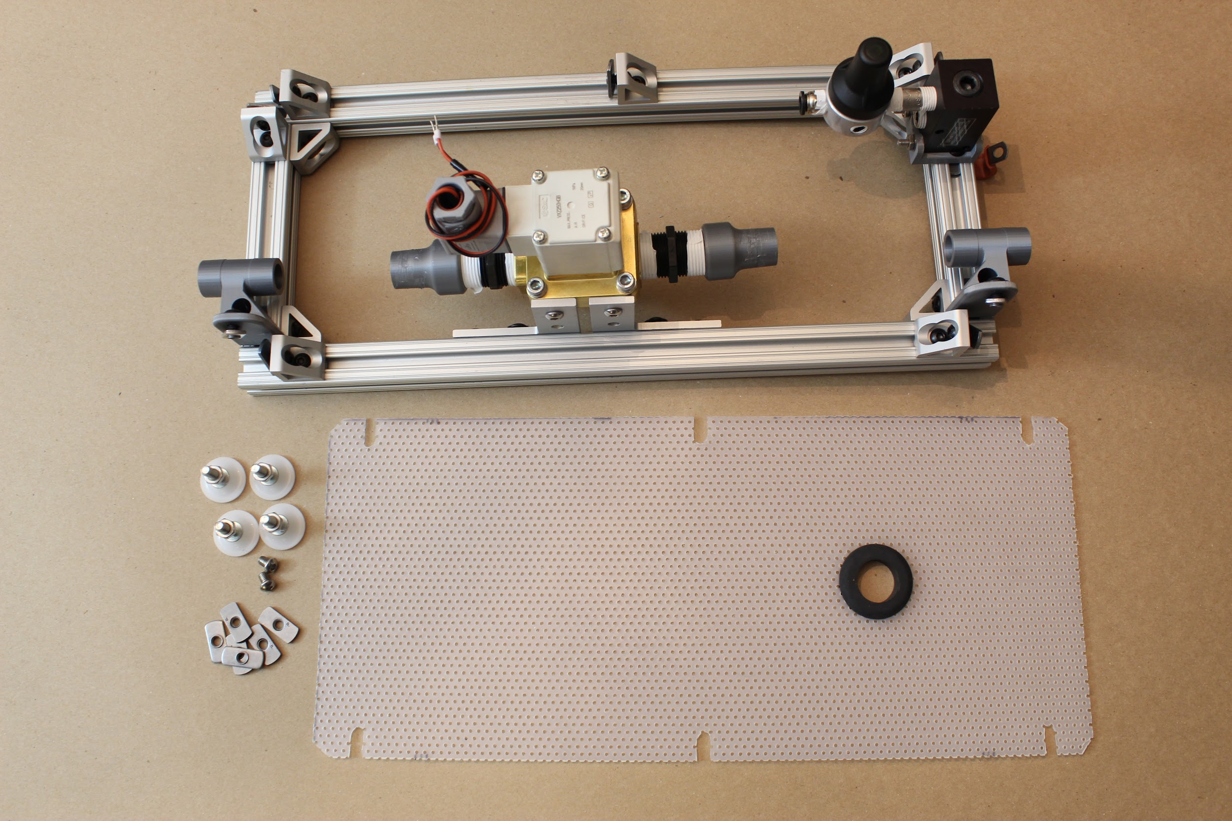
Step 14. Attach the respiratory tube segment.
Awesome- almost done with the lower level of the ventilator! As a last step, attach the short segment of respiratory circuit between the “Expiratory outlet bracket to PEEP” and the nearest “22mm to .75NPTM adapter”. You’ll be able to twist this on by hand.
2.2 Assembling the frame sides
Step 1. Attach the proportional valve to its mount.
Use the two socket head screws (6mm long) to attach the proportional valve to the 3D printed “proportional valve bracket”. The inlet should be to the right in the orientation shown below.
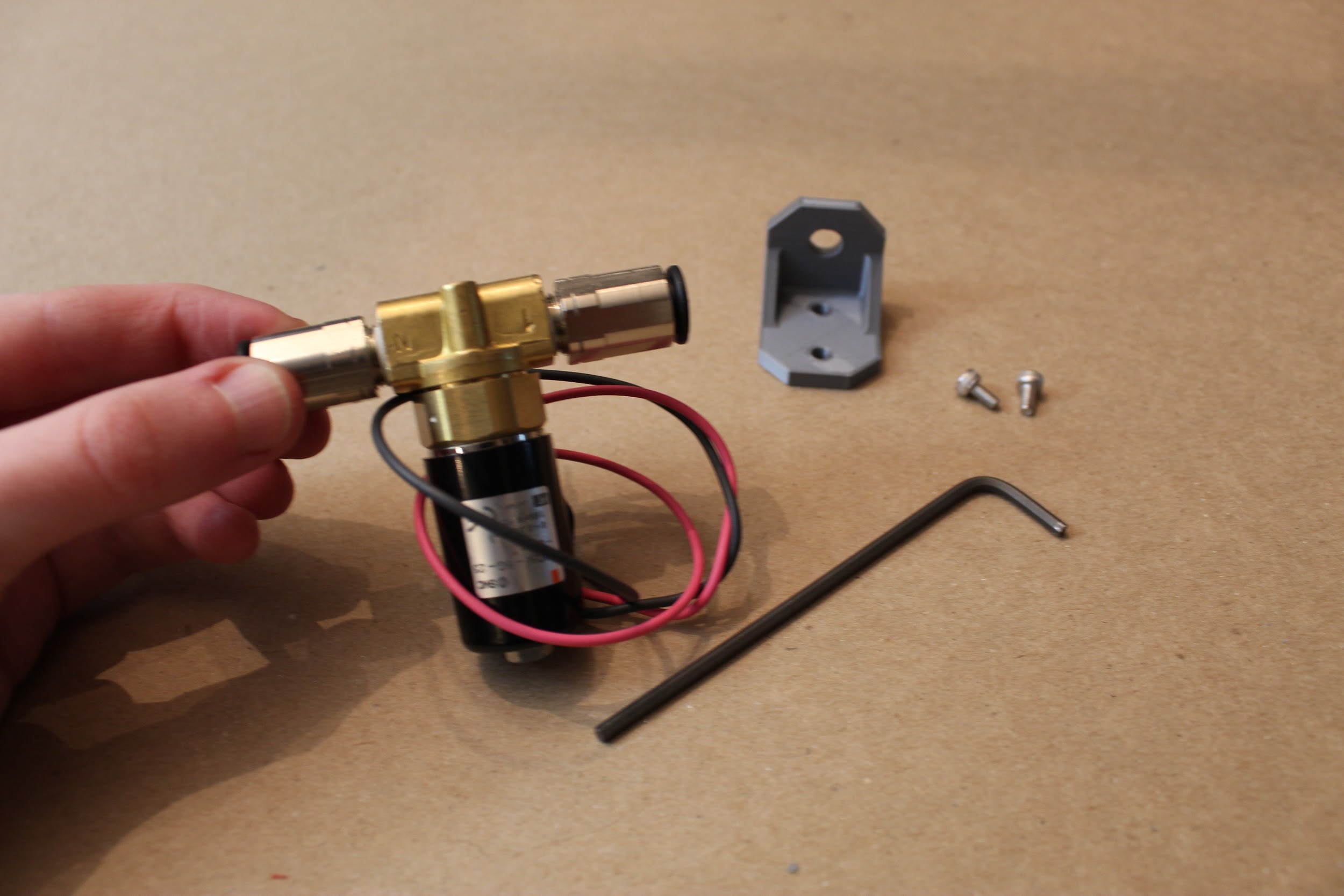
Step 2. Attach the pressure relief valve to its adapters.
Assemble the T-line push-to-connect adapter, to a female-female ¼” NPT connector, and finally to the Nylon pressure release valve.
Step 3. Attach the luer lock connectors to the luer lock filter mount.
These pieces will screw in, with the luer lock portions facing outwards.
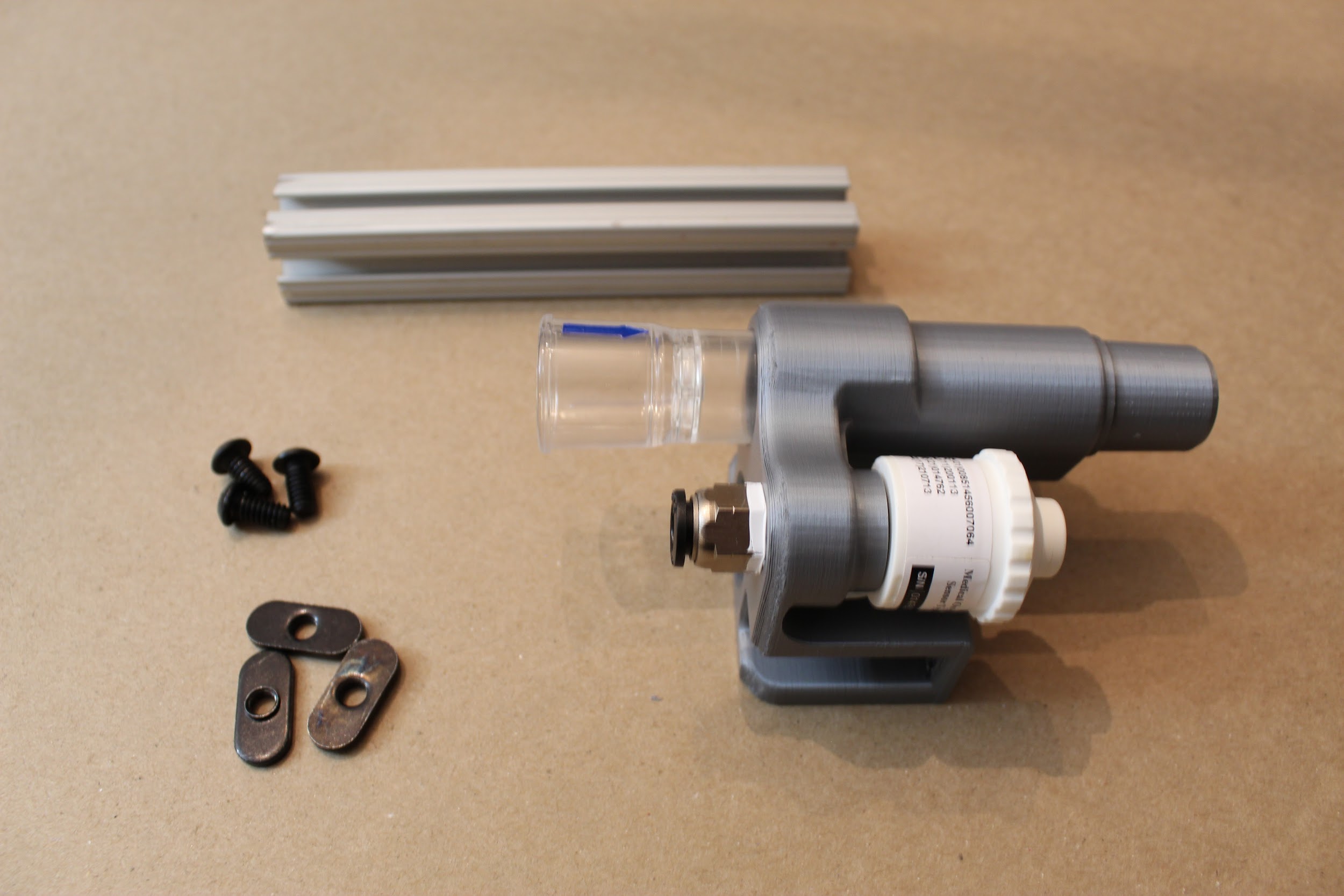
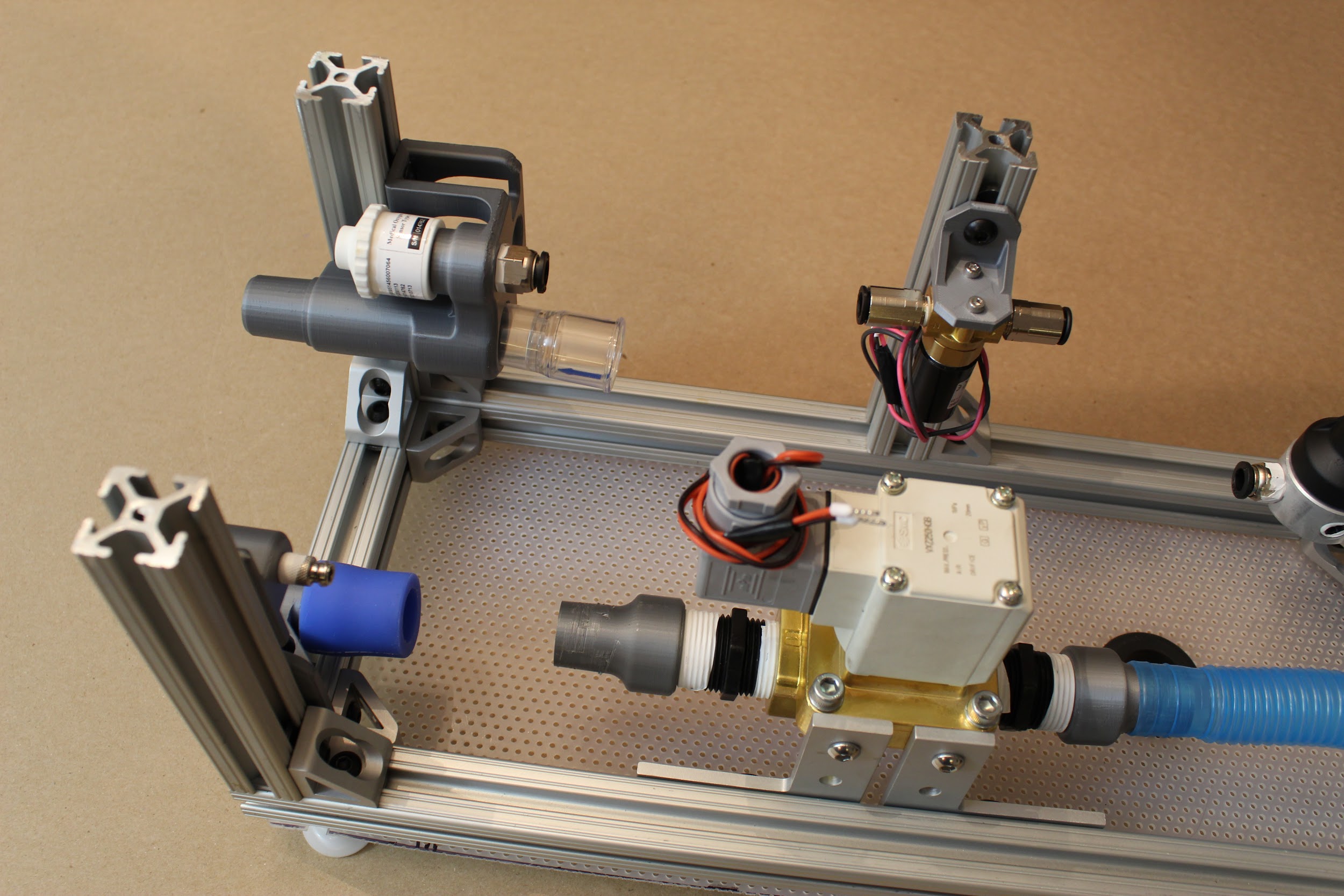
Step 4. Assemble the sensor atrium.
Attach the ¼” NPT push-to-connect adapter, check valve, and oxygen sensor into the appropriate holes in the “Sensor Atrium Manifold”, as shown. Do not push the check valve into the device too far, as it may restrict air flow within the atrium.
Step 5. Attach sensor atrium to a short 80/20, and then to the device.
Affix button head screws/nuts to the sensor atrium, with hex nuts facing
towards one another, as shown. Slide the hex nuts along T-slots on
either side of a short (5 ⅞”) 80/20 piece; then insert this vertically
into the device as shown. Tighten into place via the hex screws on the
lower gusset (corner) brackets.
*Note: If you are attaching the side panels, be sure to use a SHORT
nut on the sensor atrium (the nut on the side with two, farther from the
oxygen sensor), and keep the short side facing down when inserting. This
will allow the sensor atrium to drop lower and align with the holes in
the front panel.
Step 6. Attach the second vertical leg, along the “Expiratory DAR filter bracket”.
As before, slide a short (5 ⅞”) 80/20 piece into the position shown, then tighten the hex screws.
Step 7. Attach the luer lock filter bracket to the newly inserted
80/20 leg.
*Note: If you’re attaching the side panels, use another SHORT 80/20
nut in the uppermost spot on the bracket. We’ll want this part to be as
high as possible to match up with the holes on the front panel.
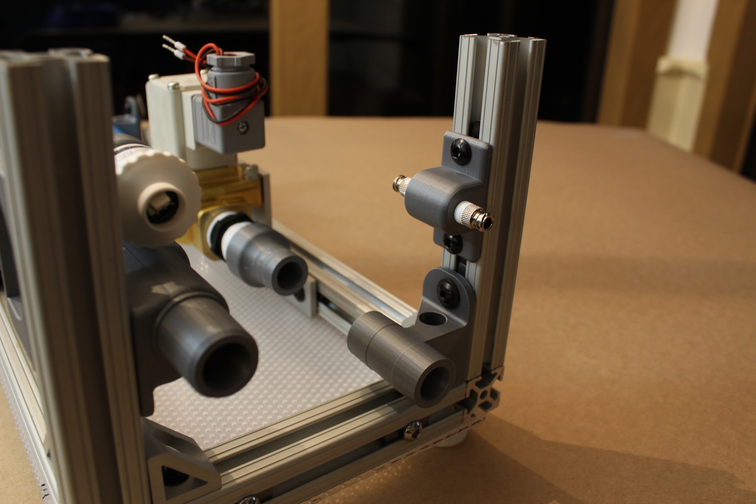
Step 8. Attach the third vertical 80/20 leg, then attach the proportional valve mount.
Insert a third, short (5 ⅞”) 80/20 piece, then tighten the hex screw to hold it in place. Use another standard hex screw/nut to attach the proportional valve mount to this piece, towards the inside of the device, such that the push-to-connects roughly align vertically with the push-to-connect on the sensor atrium.
Step 9. Attach the final two vertical 80/20 pieces in the remaining corners.
*Note: If you’re attaching the side panels, now is the time to insert 80/20 nuts on the vertical 80/20 pieces as well as the long 80/20 pieces on the lower frame.
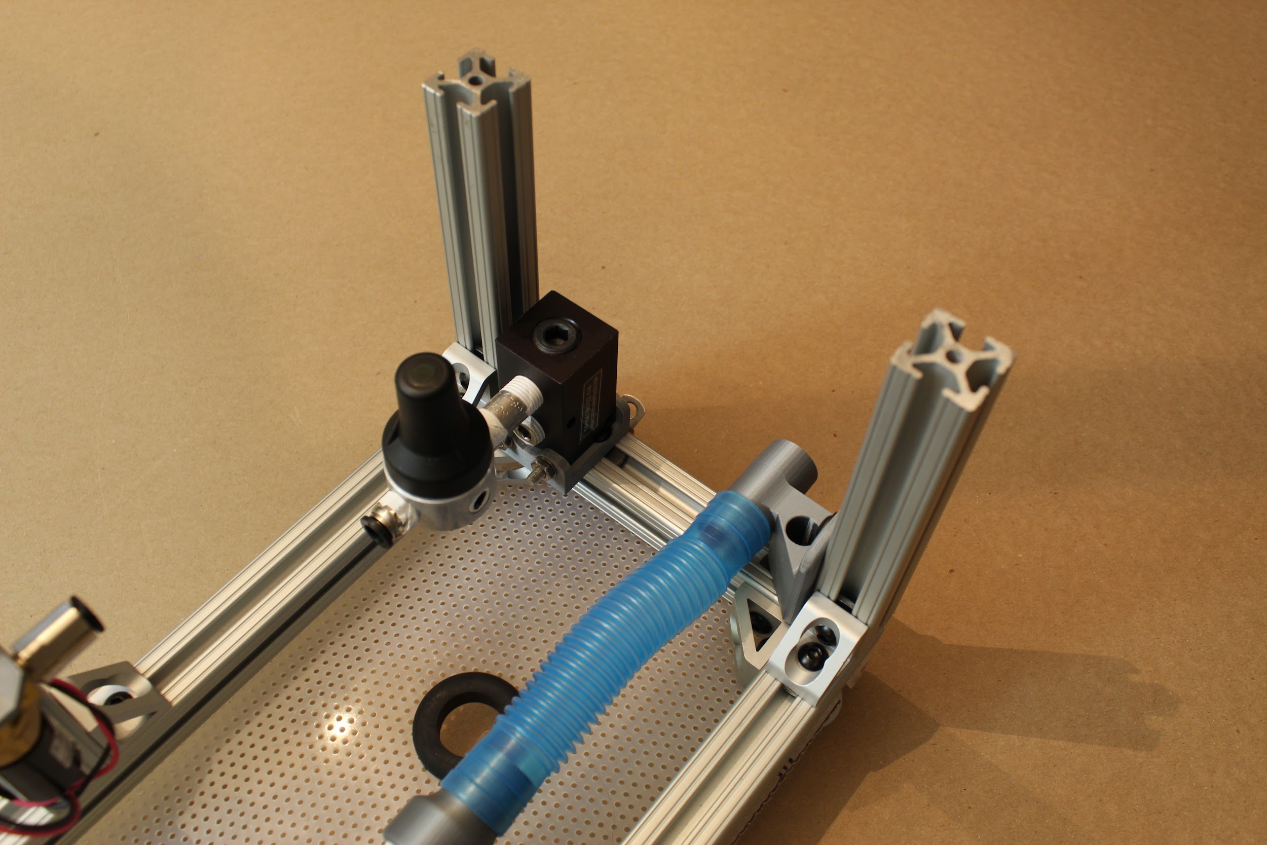
Step 10. Attach the D-Lite.
Attach a blue silicone connector to the “Expiratory DAR filter bracket), on the side within the device. Then, insert the D-Lite between the silicone connector and the nearest “22mm to .75 NPTM adapter”, adjusting the position of the expiratory solenoid assembly until the D-lite is firmly connected at each end. The smaller end of the D-lite should fit within the “22mm to .75 NPTM adapter”. Then, use an Allen key to tighten the hex screws on the 90 degree angle brackets to maintain the position of the solenoid.
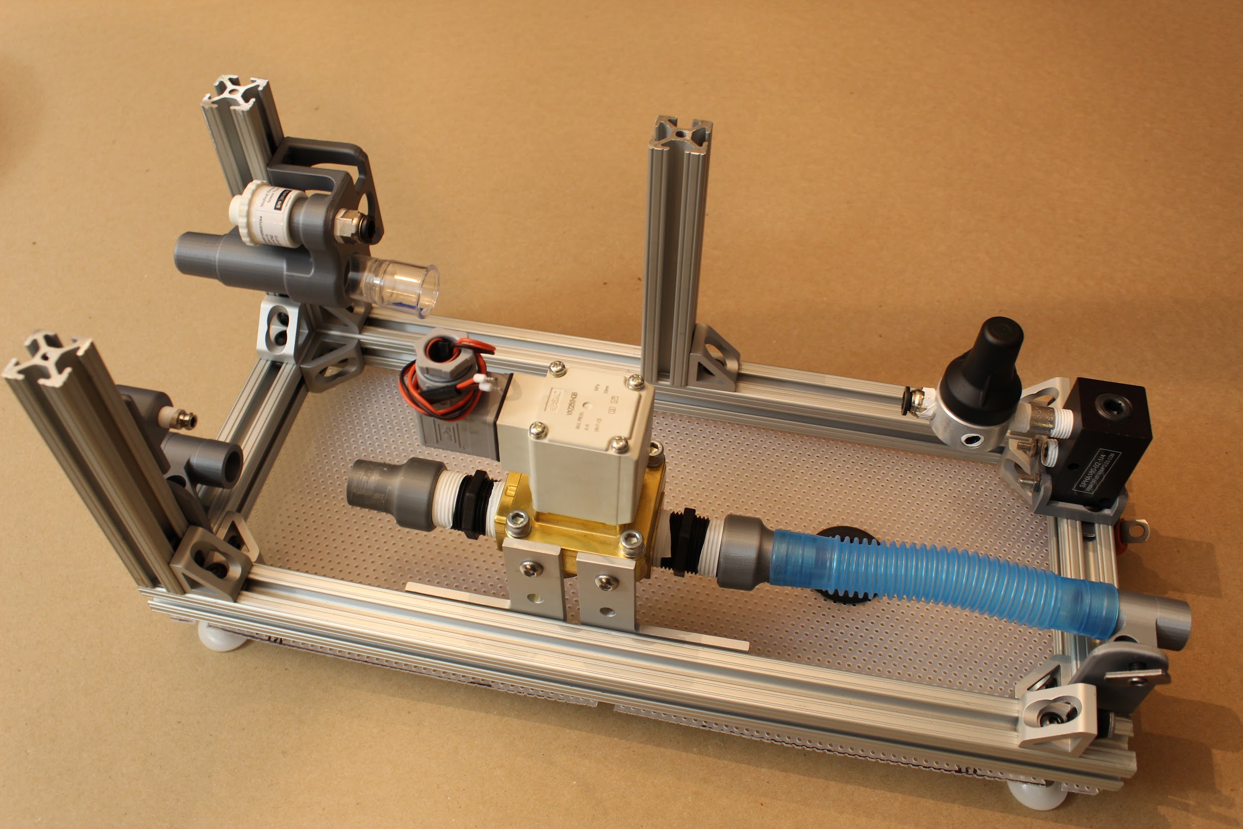
Step 11. Attach the pressure release valve and pneumatic tubing.
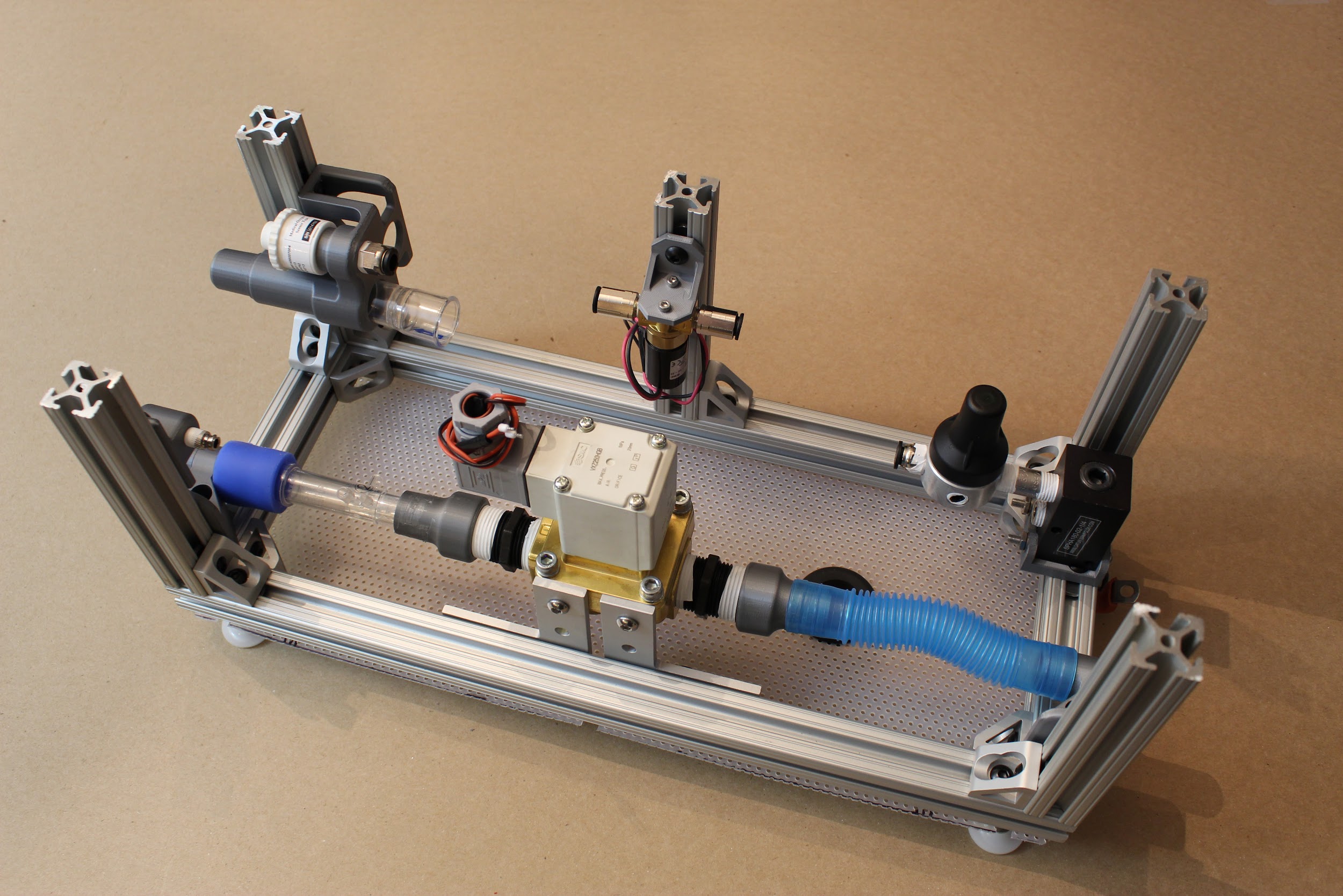
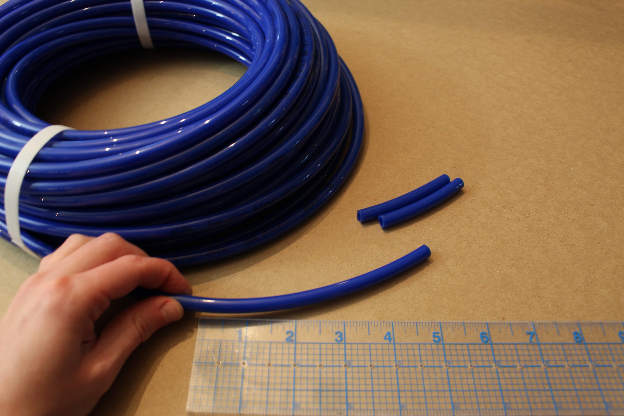
Cut the pneumatic tubing into three segments: two of length 2.5” (6.35cm), and one of length 5.5” (13.97cm). Insert the long piece between the push-to-connect adapters attached to the pressure regulator and proportional valve. Insert the two shorter tubes into either push-to-connect on the pressure relief valve assembly; then attach these between the sensor atrium and proportional valve push-to-connects, as shown. These tubing lengths should keep the proportional valve fairly centered.
2.2 Assembling the frame top
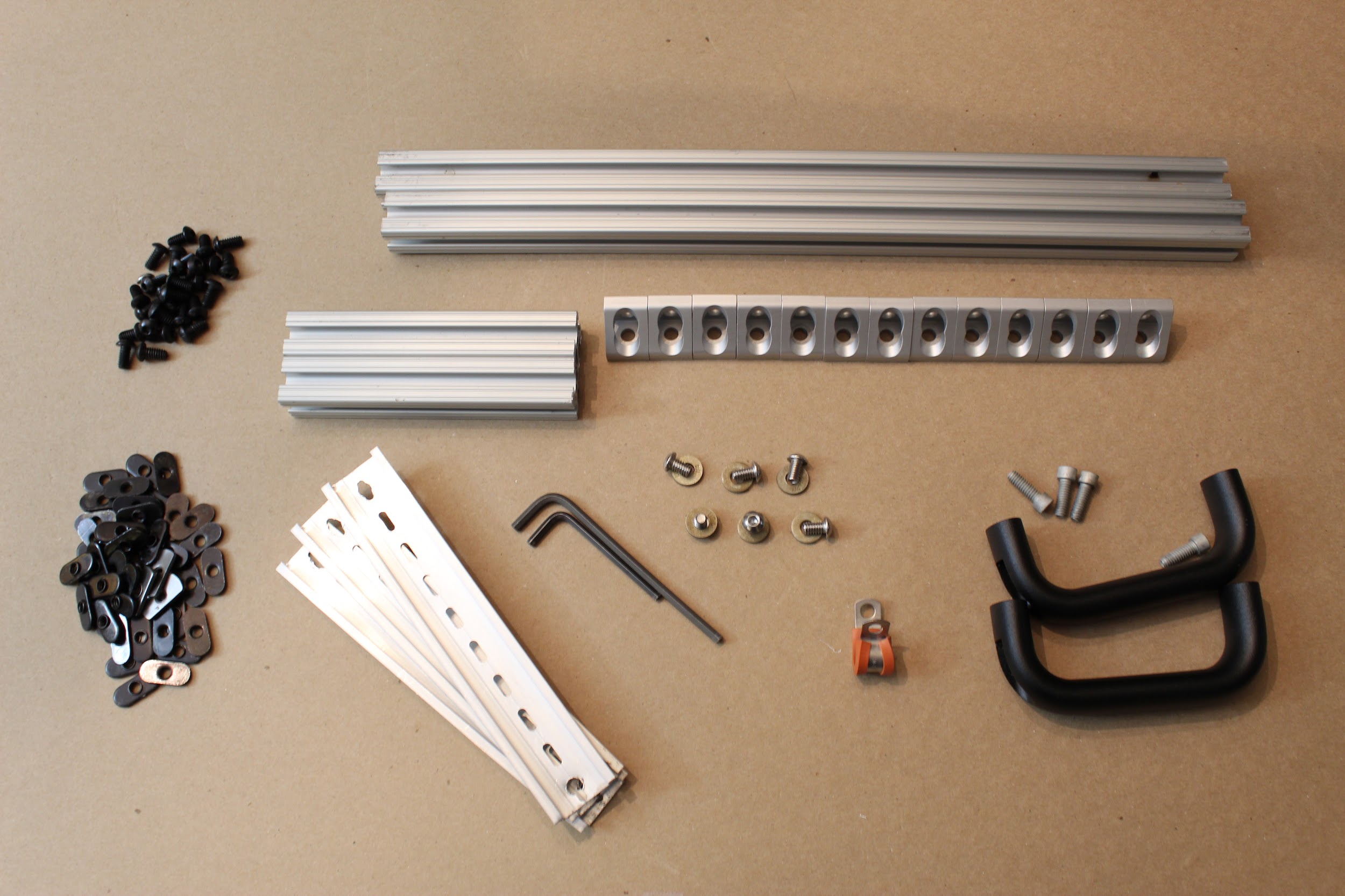
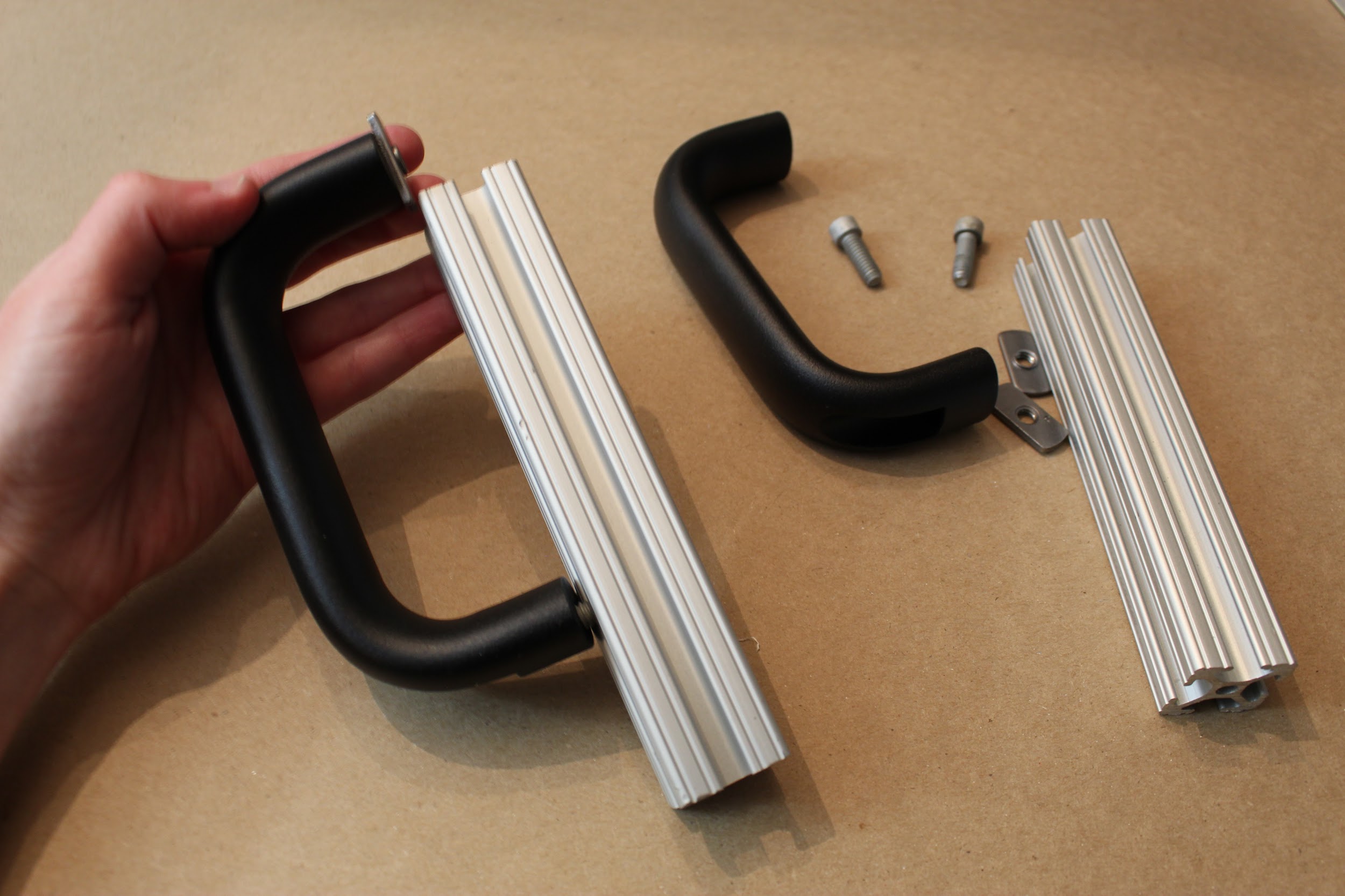
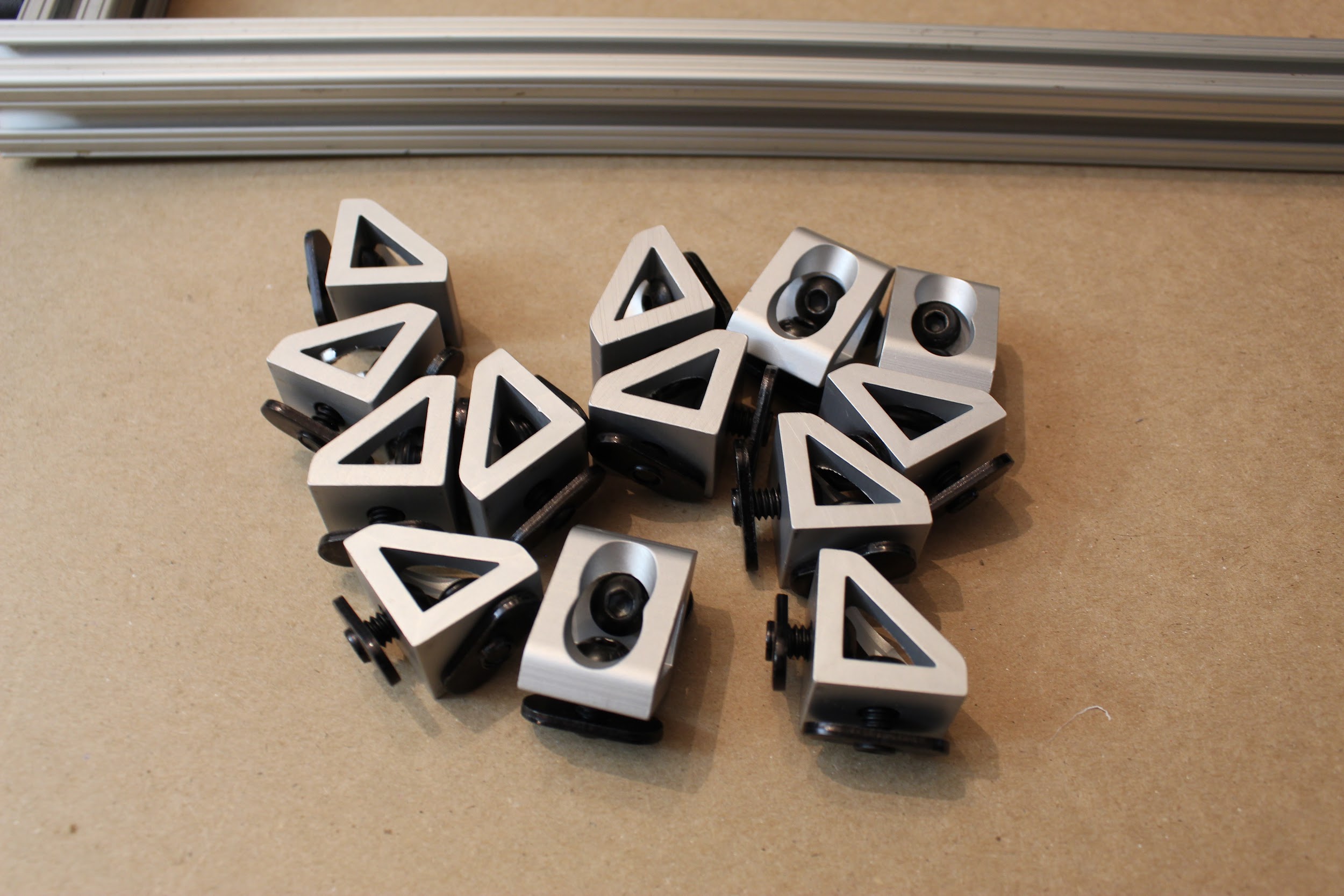
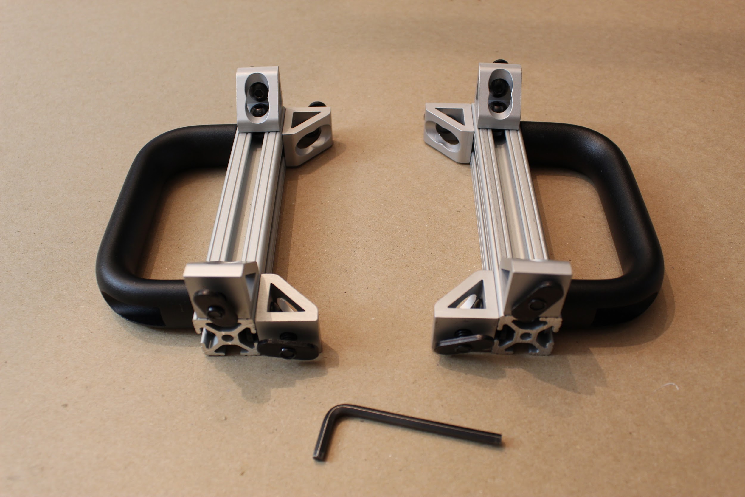
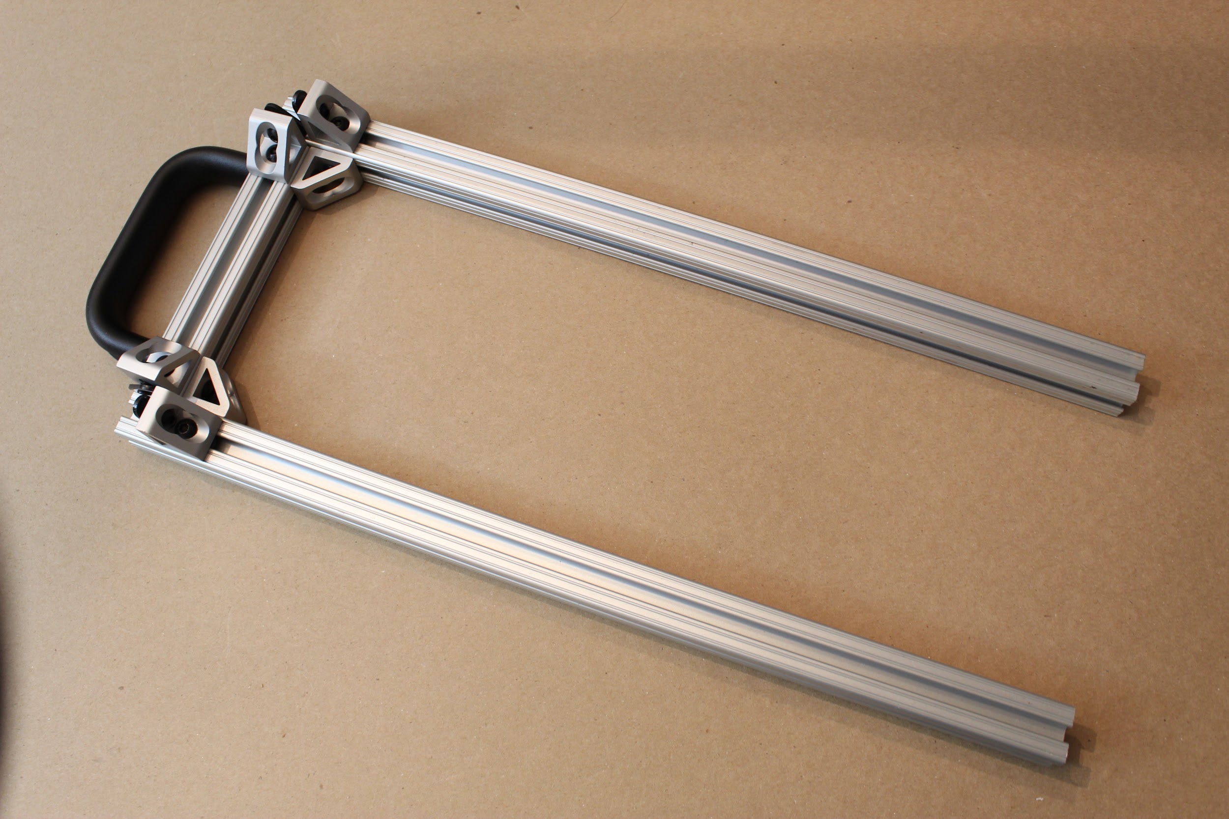
Step 1. Attach the lifting handles.
Use the lifting handle screws (SHCS_0.25-20x0.75_Gr8_ASTM_F1136), with standard hex nuts, to mount the lifting handles to two short (5 ⅞”) pieces of 80/20, such that the handles are centered on the pieces.
Step 2. Prepare all the remaining gusset (corner) brackets.
Attach the hex screws/nuts loosely to the 13 remaining gusset (corner) brackets, so that they can be attached readily in future steps.
Step 3. Attach gusset (corner) brackets, as shown.
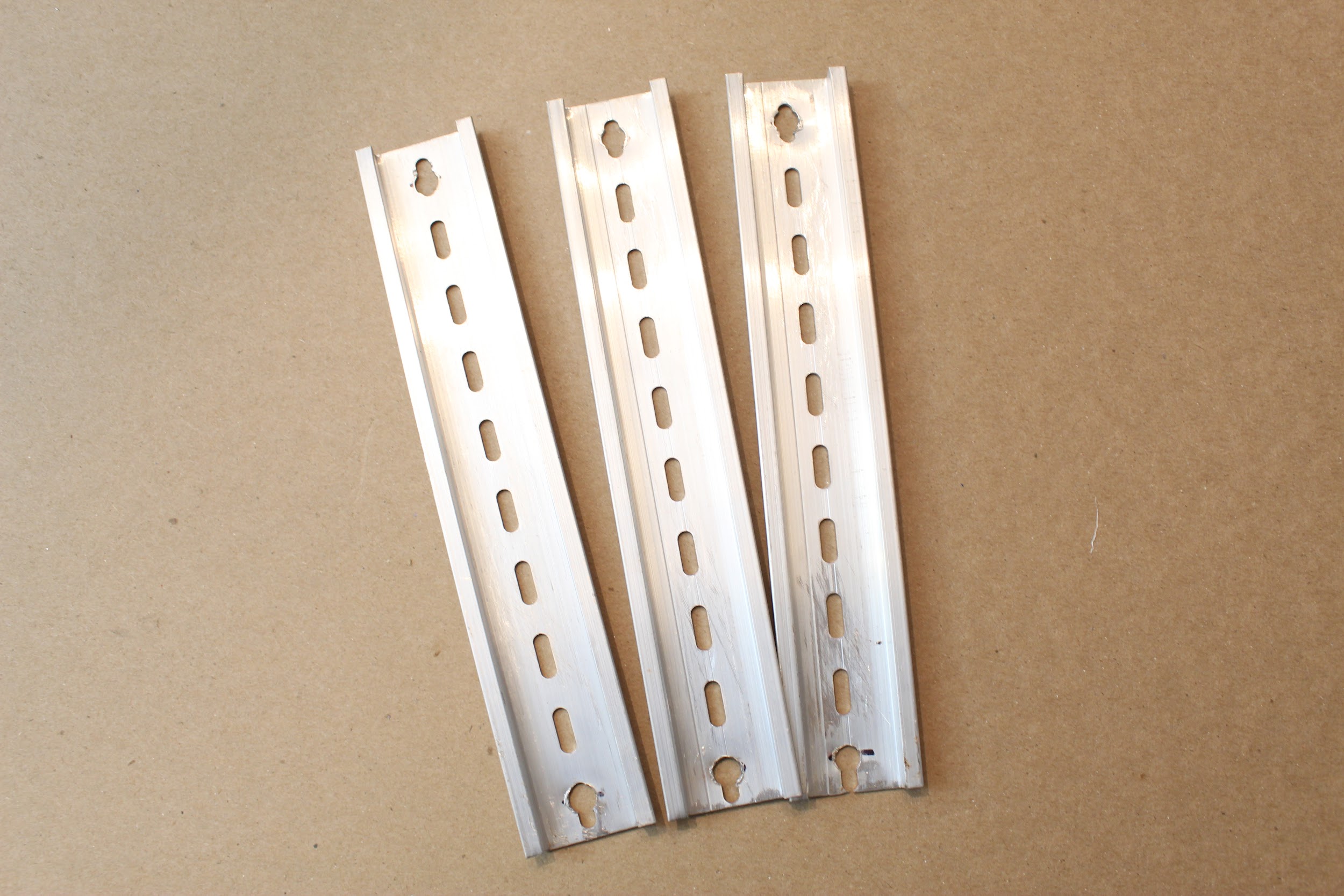
Step 4. Cut and punch DIN rail pieces.
Cut the DIN rail to 7 ⅞” (20.0025cm) lengths, punching or drilling holes ½” (1.27cm) from each edge large enough to support the standard button head hex screws.
Step 5. Attach the DIN rails and assemble the rest of the top level.
Slide two long (17 ⅞”) 80/20 pieces onto one of the shorter pieces,
and screw in place. Add an additional gusset (corner) bracket to each long leg, as shown, leaving 1” of space from the end (to support a vertical piece).
Use a short (1mm) button head hex screw, a zinc washer
(W_0.25_FLAT_THICK_GR8_YELLOW_ZINC), and a standard hex nut to attach each end of the DIN rails to the frame, as shown. Slide an additional gusset (corner) bracket between the rails on one side- this will support the central vertical channel on the device.
Once the DIN rails are roughly in place (exact positions can be
adjusted later), use the remaining gusset (corner) brackets and assembled short 80/20 piece, and mirror the other side of the assembly, as shown.
Step 6. Finally, slide the top frame directly into the vertical 80/20 channels of the device, and tighten all hex screws.

Congrats! The basic hardware assembly is complete!
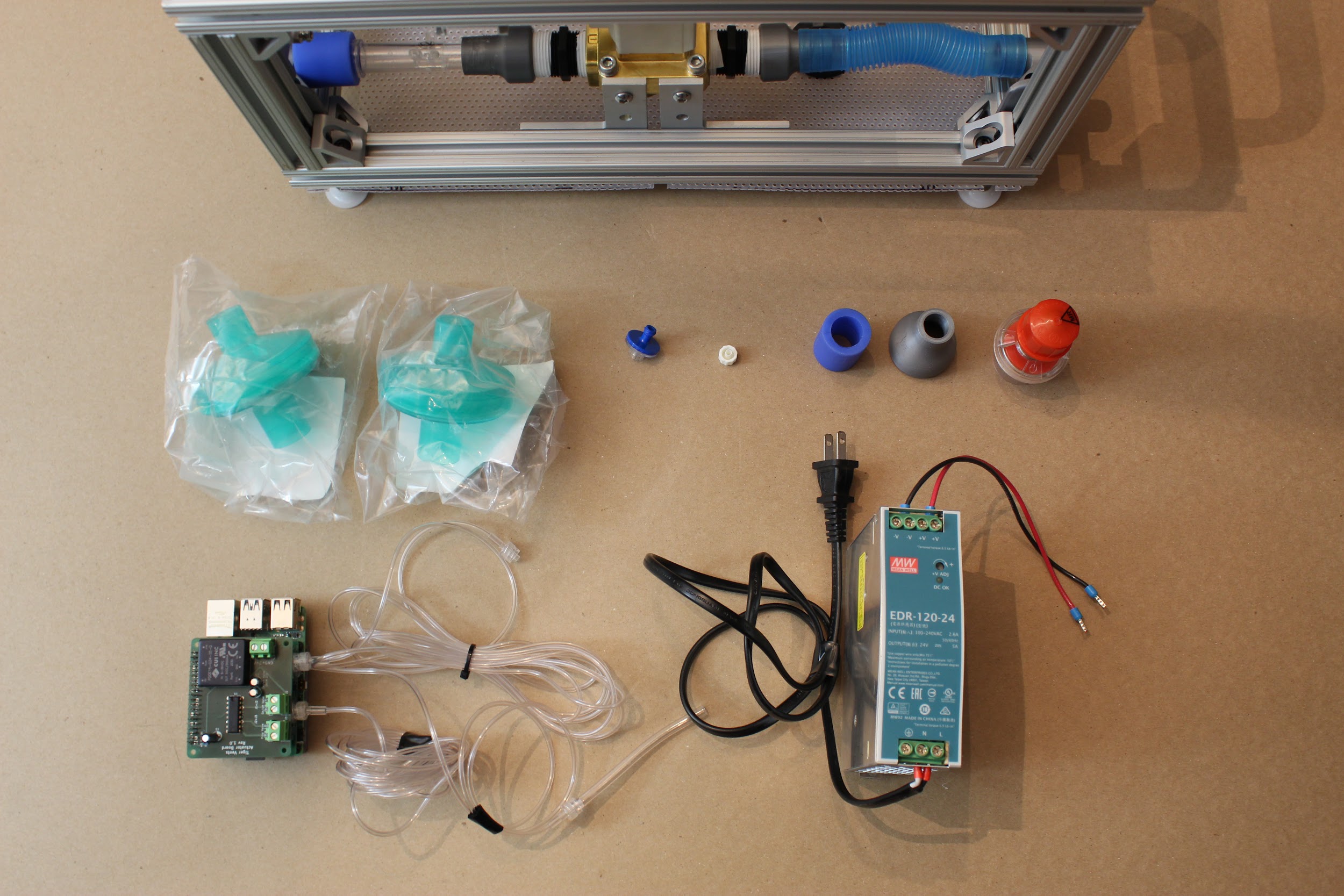
Part 3. Electronics Assembly
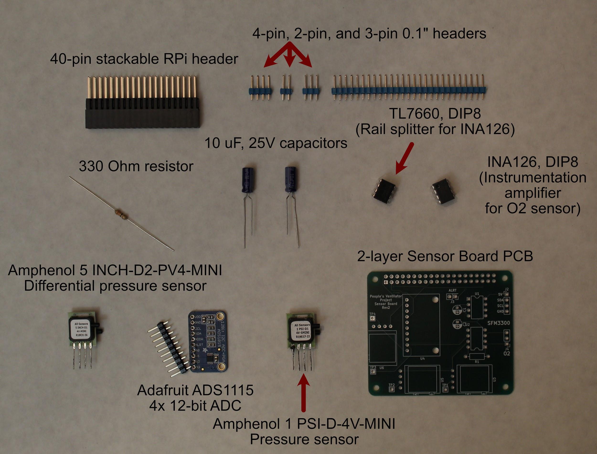
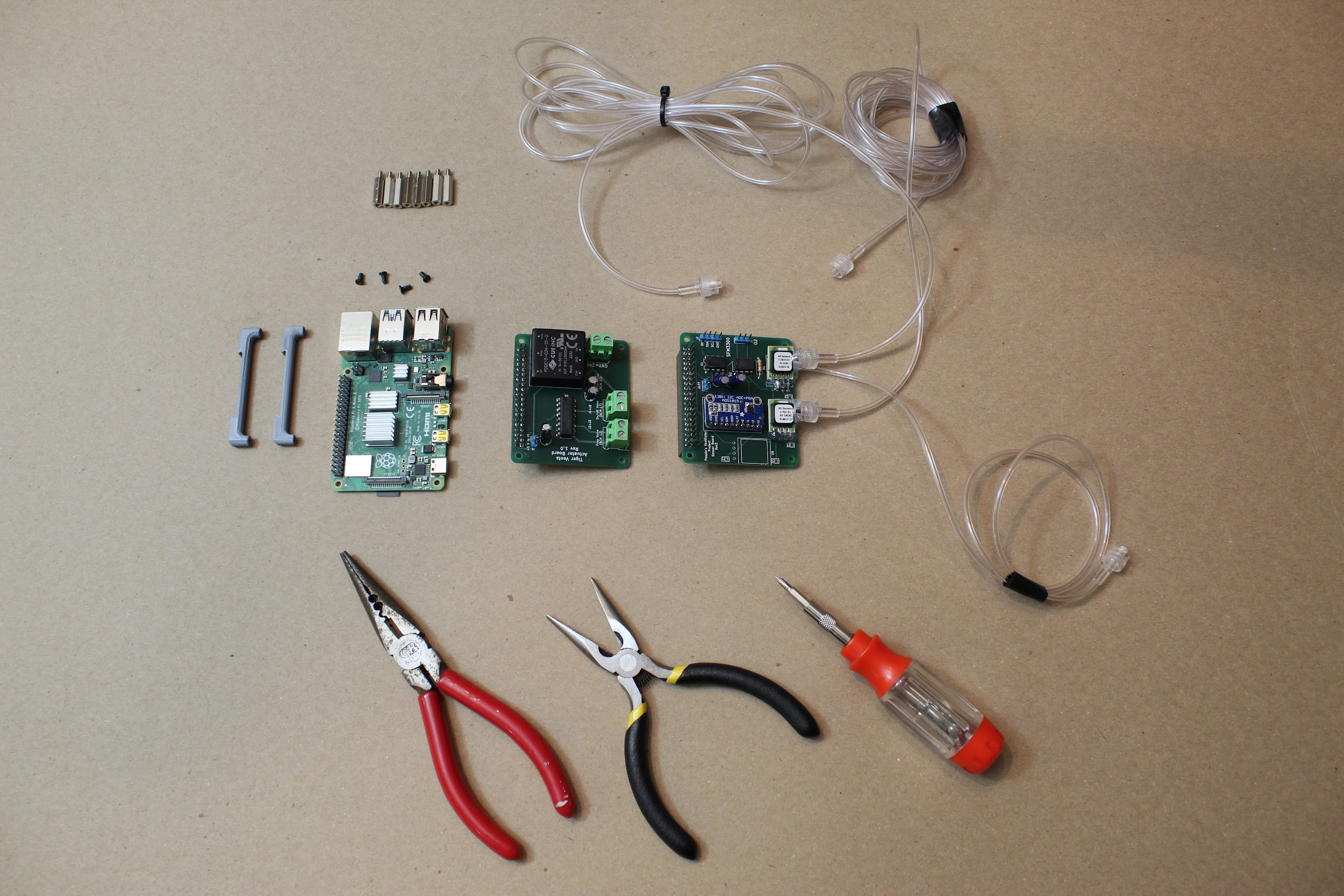
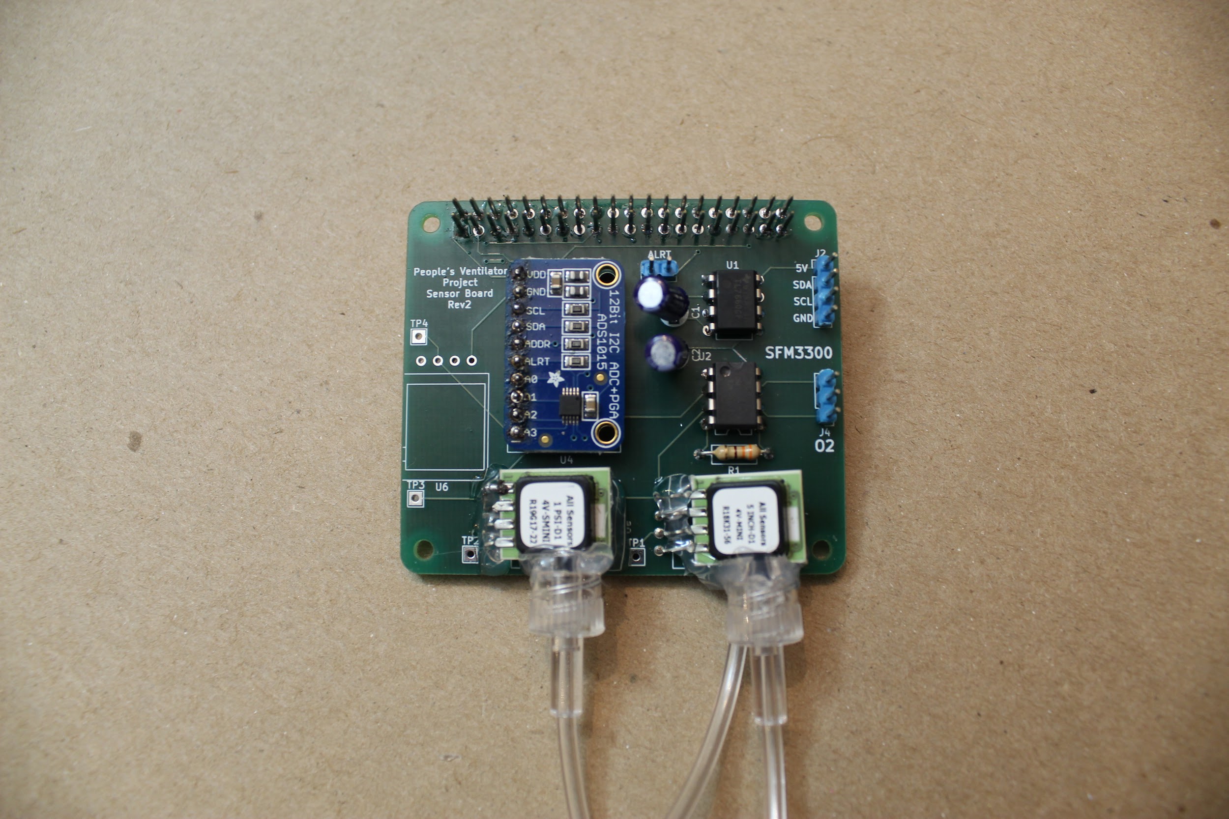
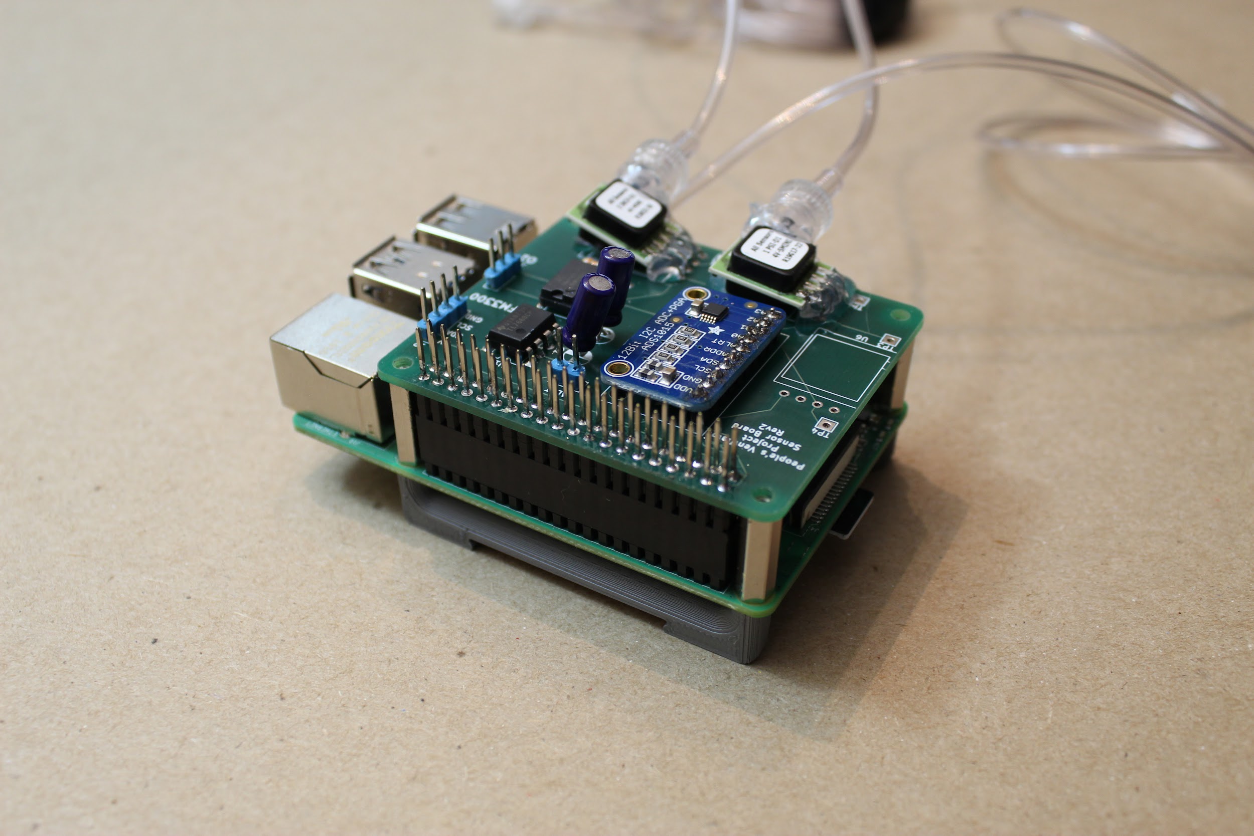
3.1 Assembling the Sensor Board
[Image of all components laid out in order/piles, with labels]
You will also need:
A soldering iron
Solder
Helping hands for holding parts while soldering
Wire cutters (for clipping off long capacitor/resistor legs)
Step 1. Solder the 40-pin stackable RPi header to the Actuator PCB.
Push the pins up from the bottom of the board, as shown, and then solder into place.
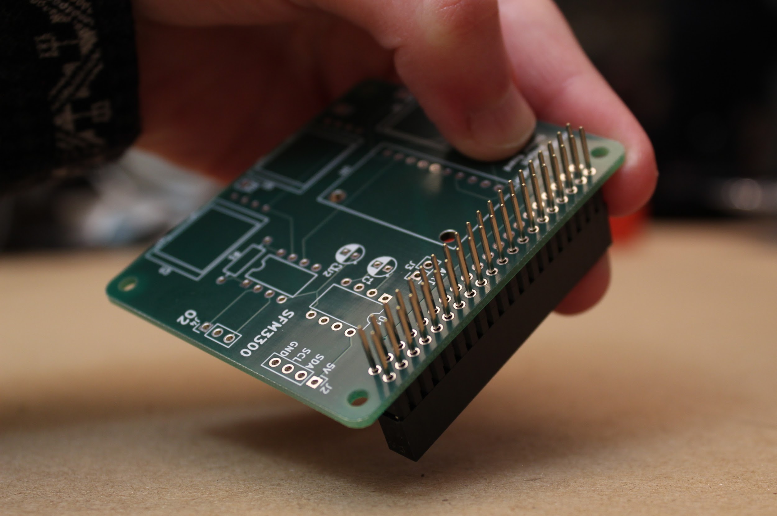
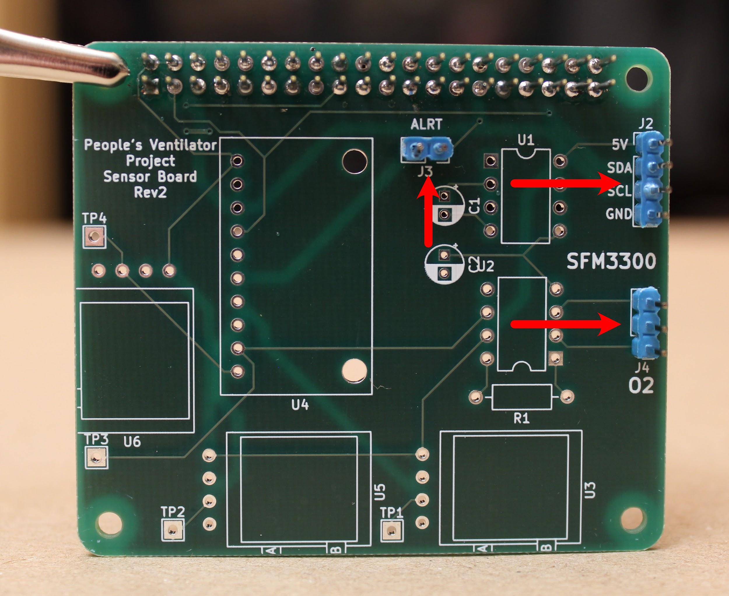
Step 2. Solder the 4-pin, 3-pin, and 2-pin 0.1” headers onto the board (positions J2, J3, J4).
Break the pins off the larger header array in units of 4, 2, and 3 using pliers. Insert the short end of the pins into the holes from the top of the board, and solder from below. This will leave the long ends of the pins sticking up vertically from the board, as shown:
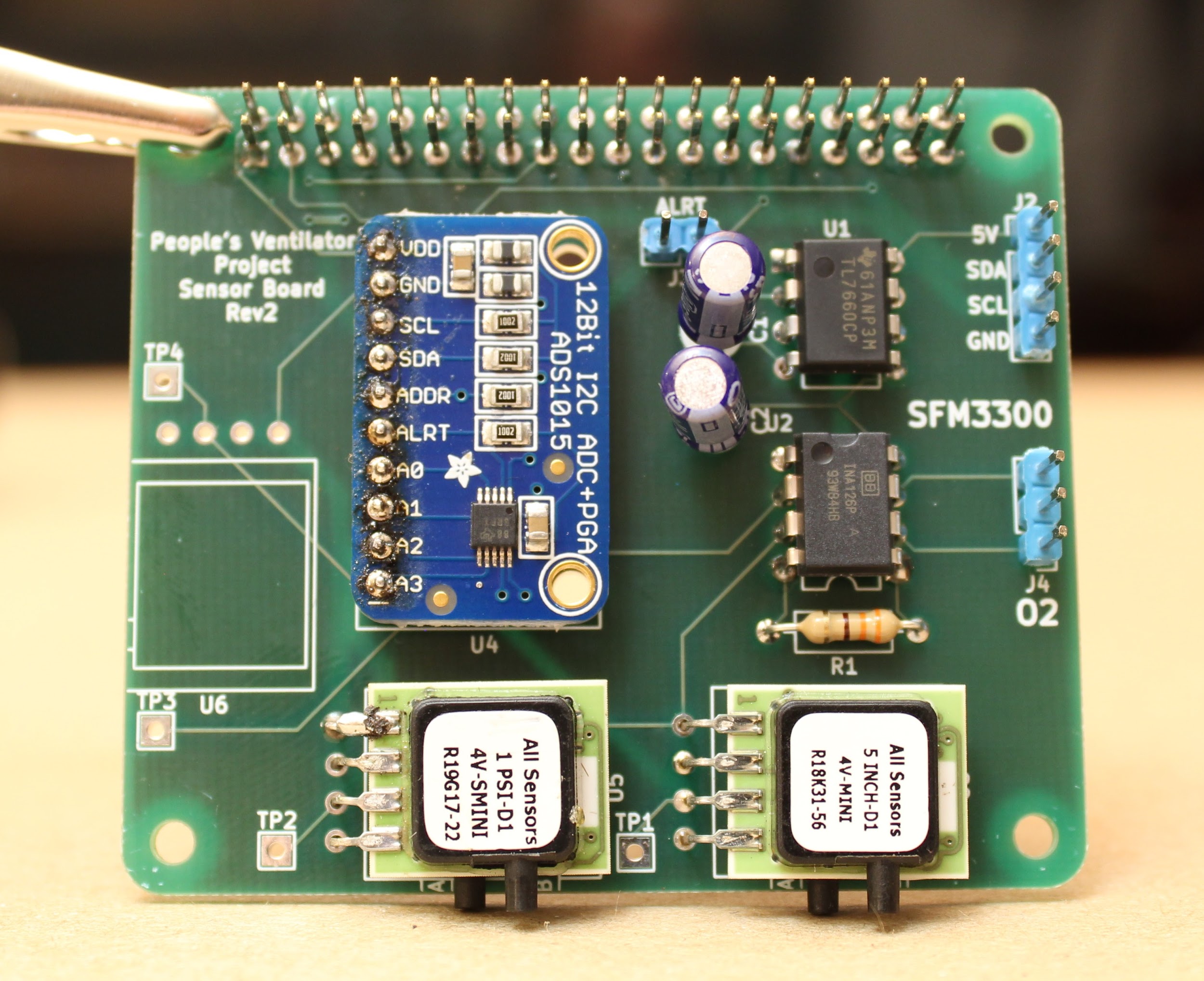
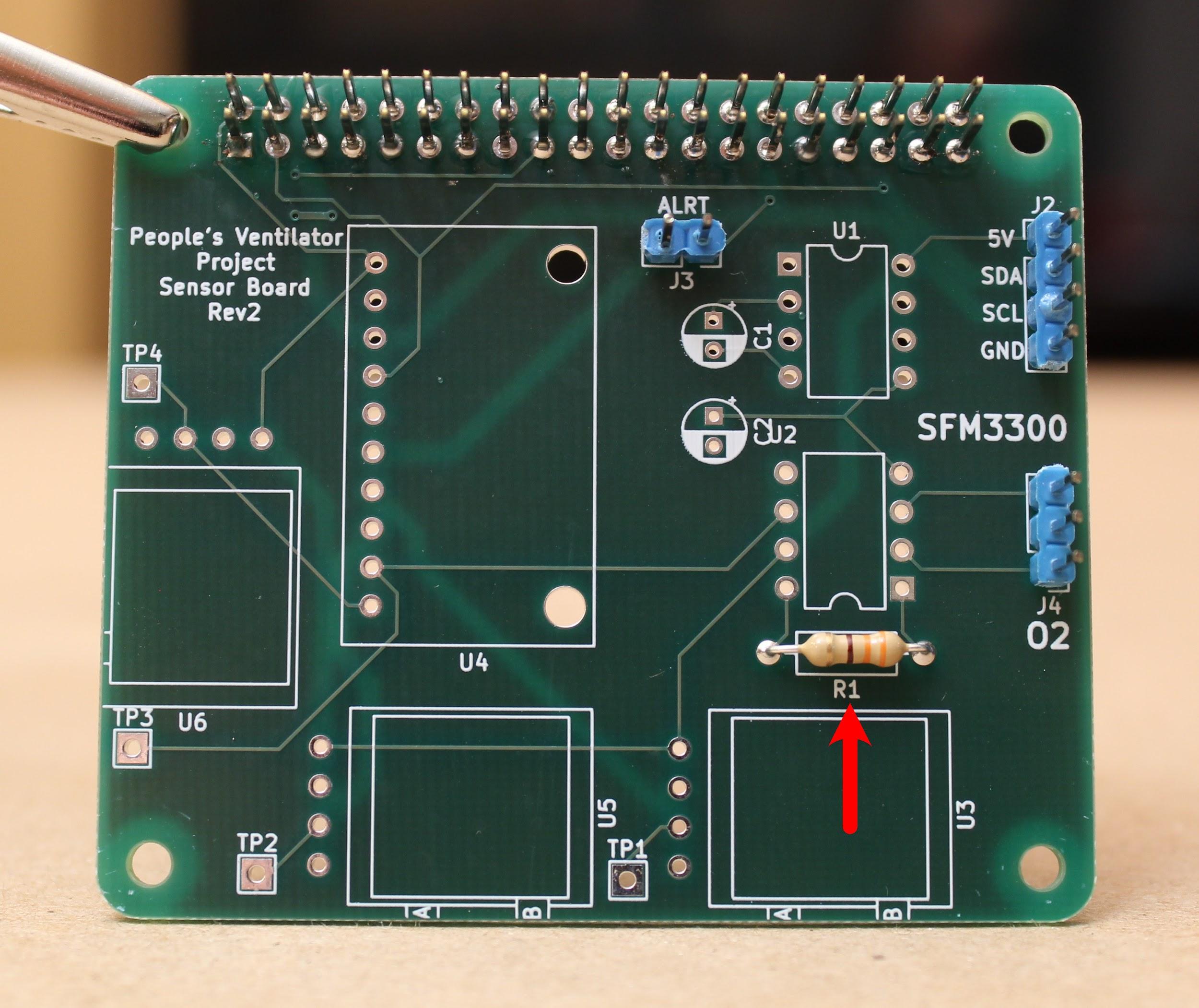
Step 3. Solder the 330 Ohm resistor onto the board (position R1).
Bend the resistor legs before inserting into the board from above. Ideally, solder the resistor in place such that the resistor is hovering just above the board. Then, snip the long legs off from the back of the board (cutting above the tiny “cone” formed by the solder) using wire cutters.
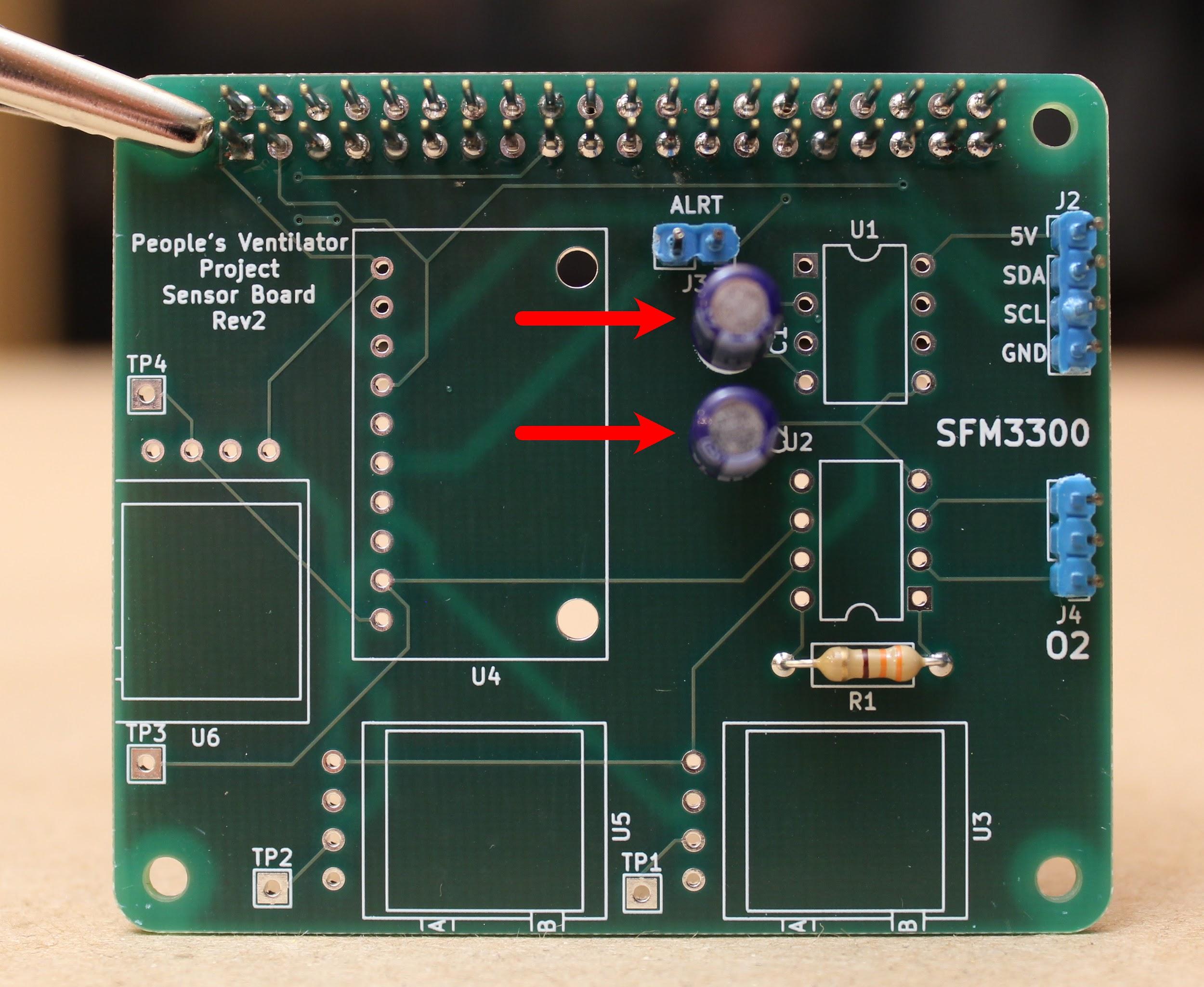
Step 4. Solder the two 10 µF, 25V capacitors onto the board (positions C1, C2).
Insert the capacitors from the top of the board until the legs snap into place. Be sure that the longer capacitor leg is inserted into the hole corresponding to the “+” sign. After soldering, snip the long legs off from the back of the board using wire cutters.
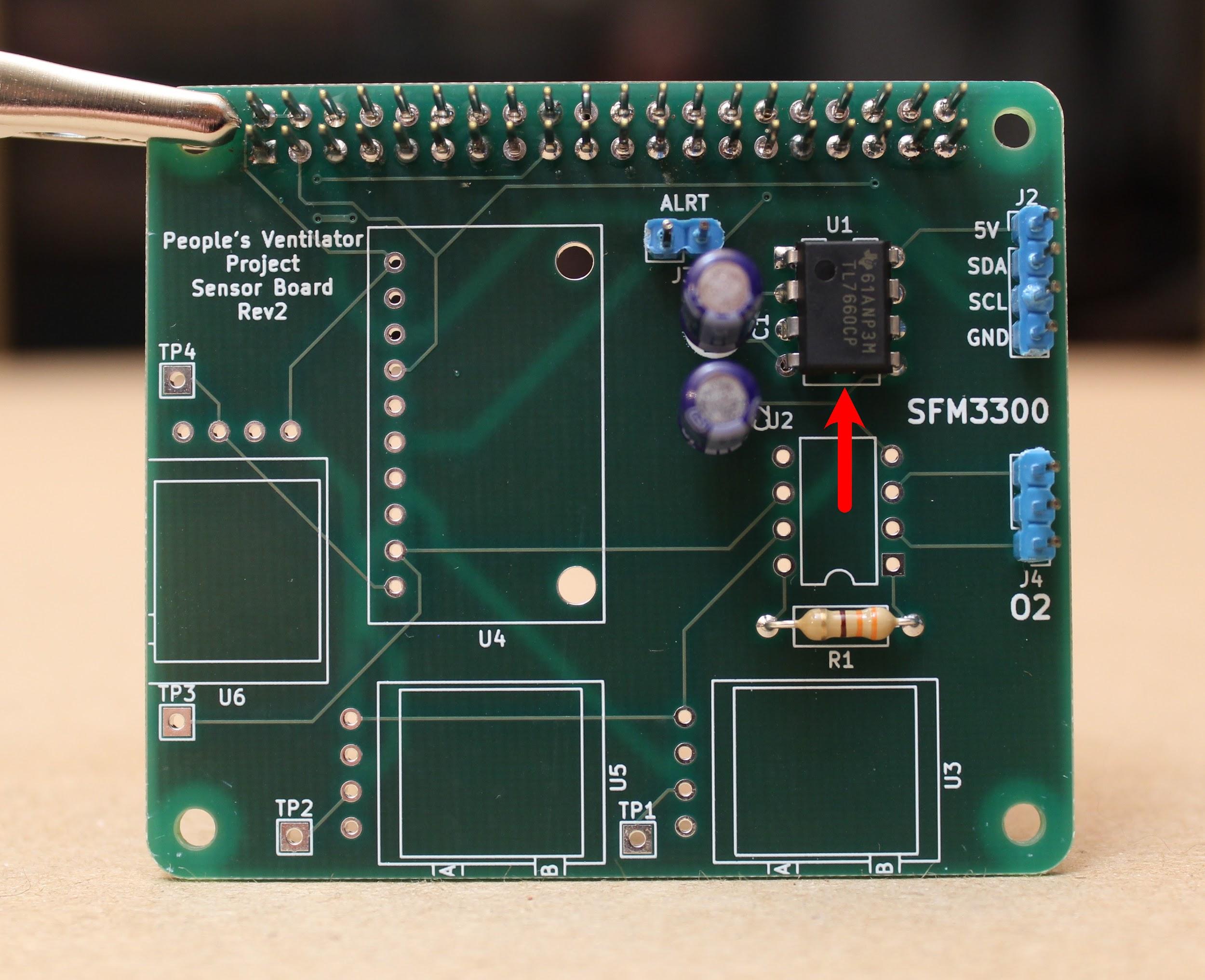
Step 5. Solder the TL7660 (the rail splitter for the INA126) onto the board (position U1).
Be sure to orient the small circle on the top of the part to the indicated notch drawn on the board.
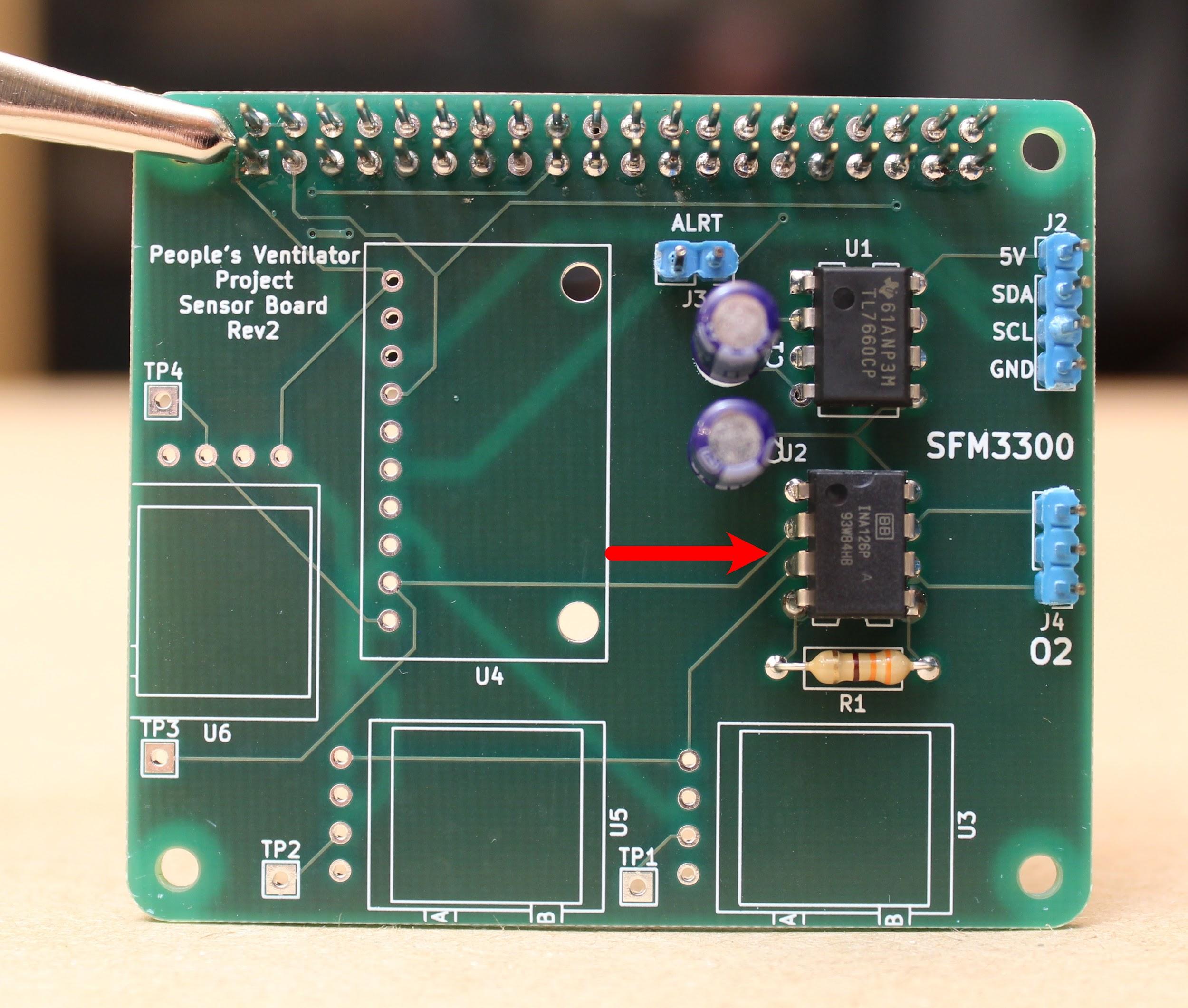
Step 6. Solder the INA126 (the instrumentation amplifier for the oxygen sensor) onto the board (position U2).
As before, make sure that the notch on the part aligns with the notch drawn on the PCB.
Step 7. Solder the Amphenol 5 INCH-D2-P4V-MINI (differential pressure sensor) onto the board (position U3).
Bend all four pins evenly and orient the part such that the black ports face towards the outside of the board. The pressure lines will attach here.
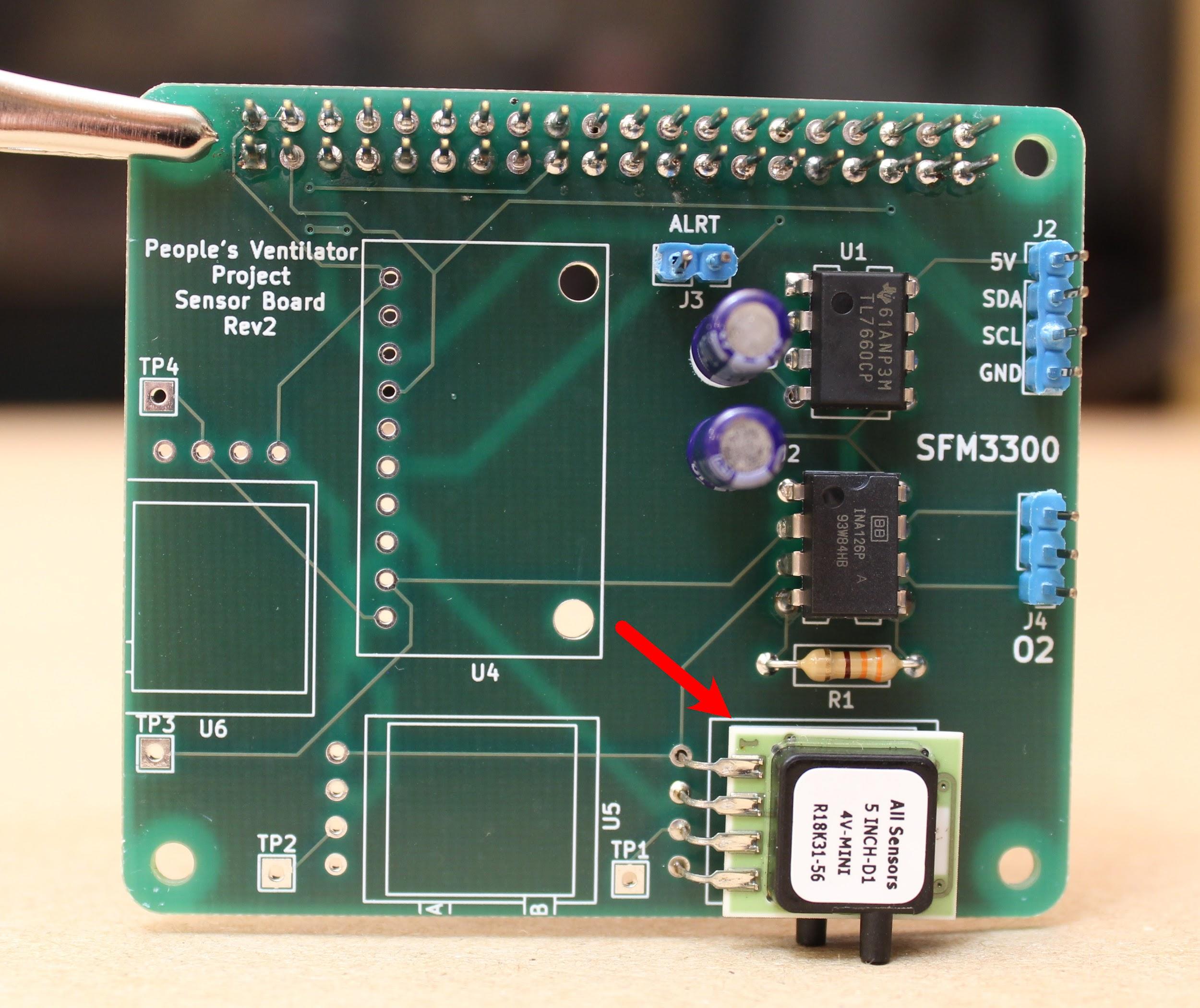
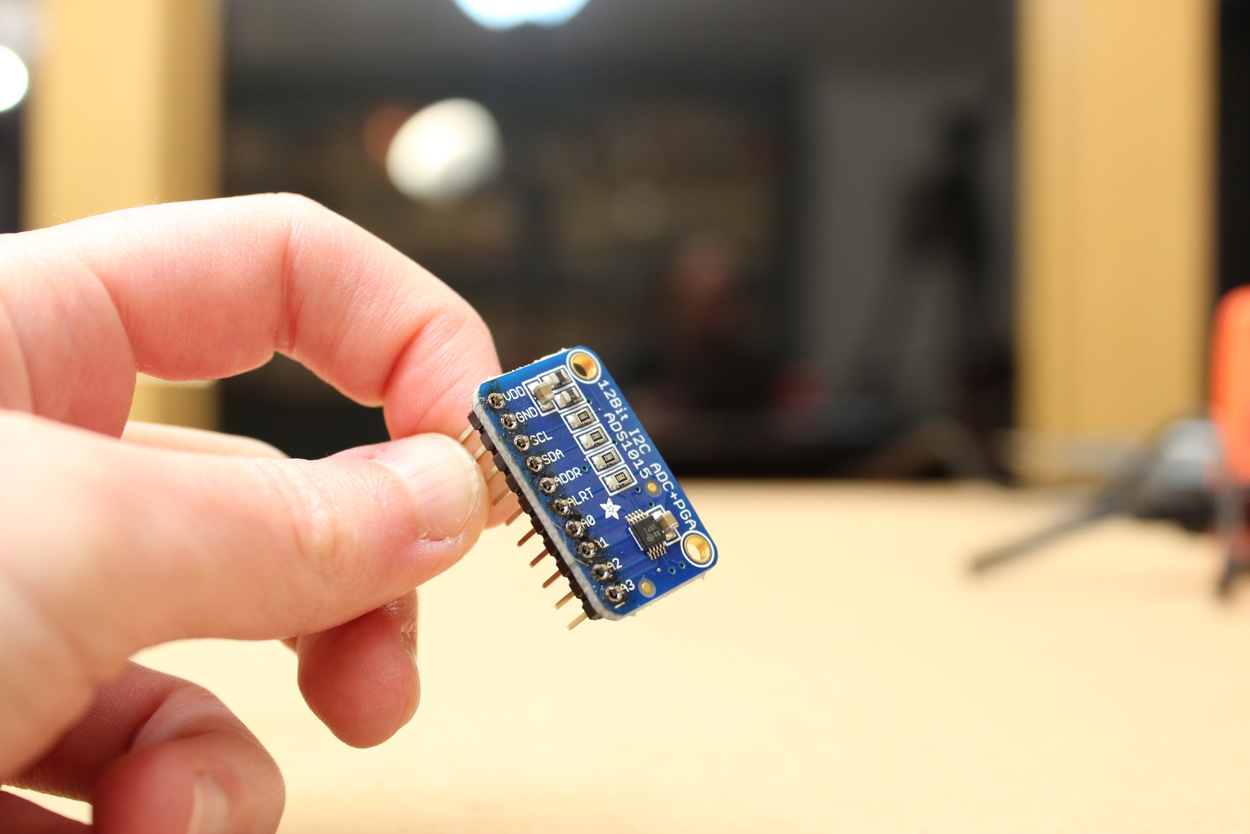
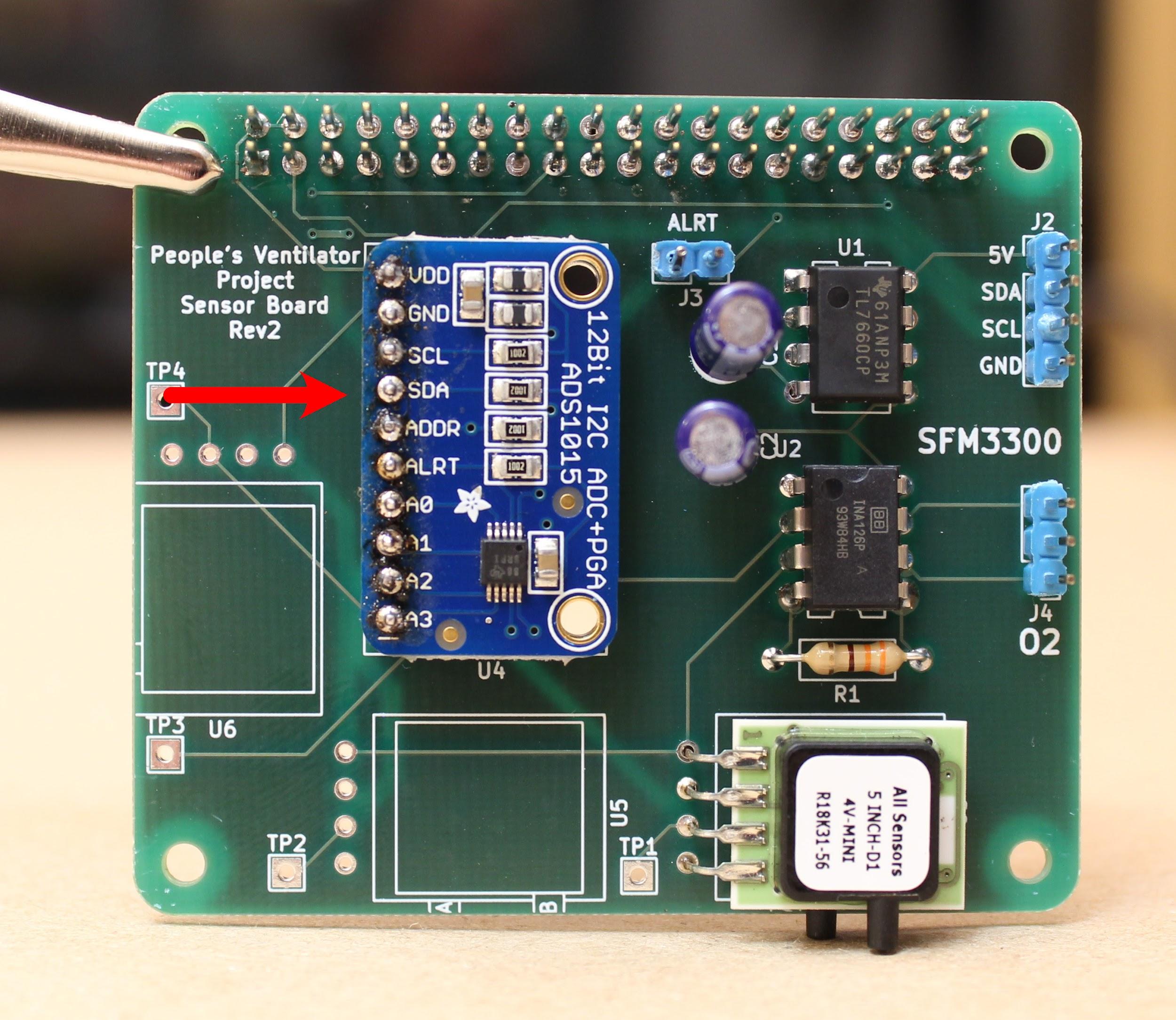
Step 8. Solder the Adafruit ADS1115 (12-bit ADC) to the board.
First, solder the pins to the ADC itself, with the long ends facing down. Then insert the pins through the board and solder from the back side.
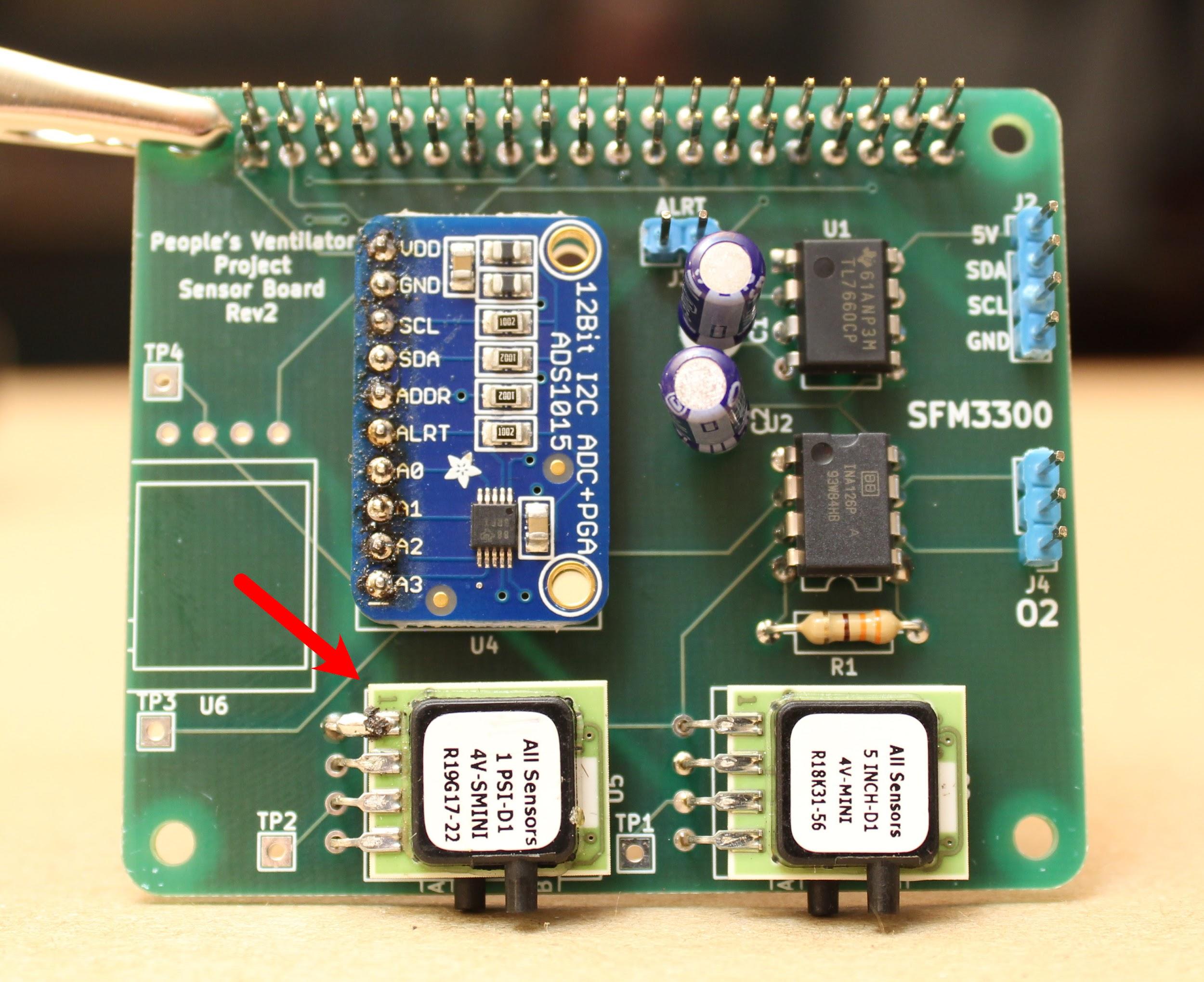
Step 9. Finally, solder the Amphenol 1 PSI-D-4V-MINI (airway pressure sensor) to the board.
As before, bend all four pins together, then insert and solder from the back side of the board. Be sure the ports are facing out: we will attach pressure lines here as well.
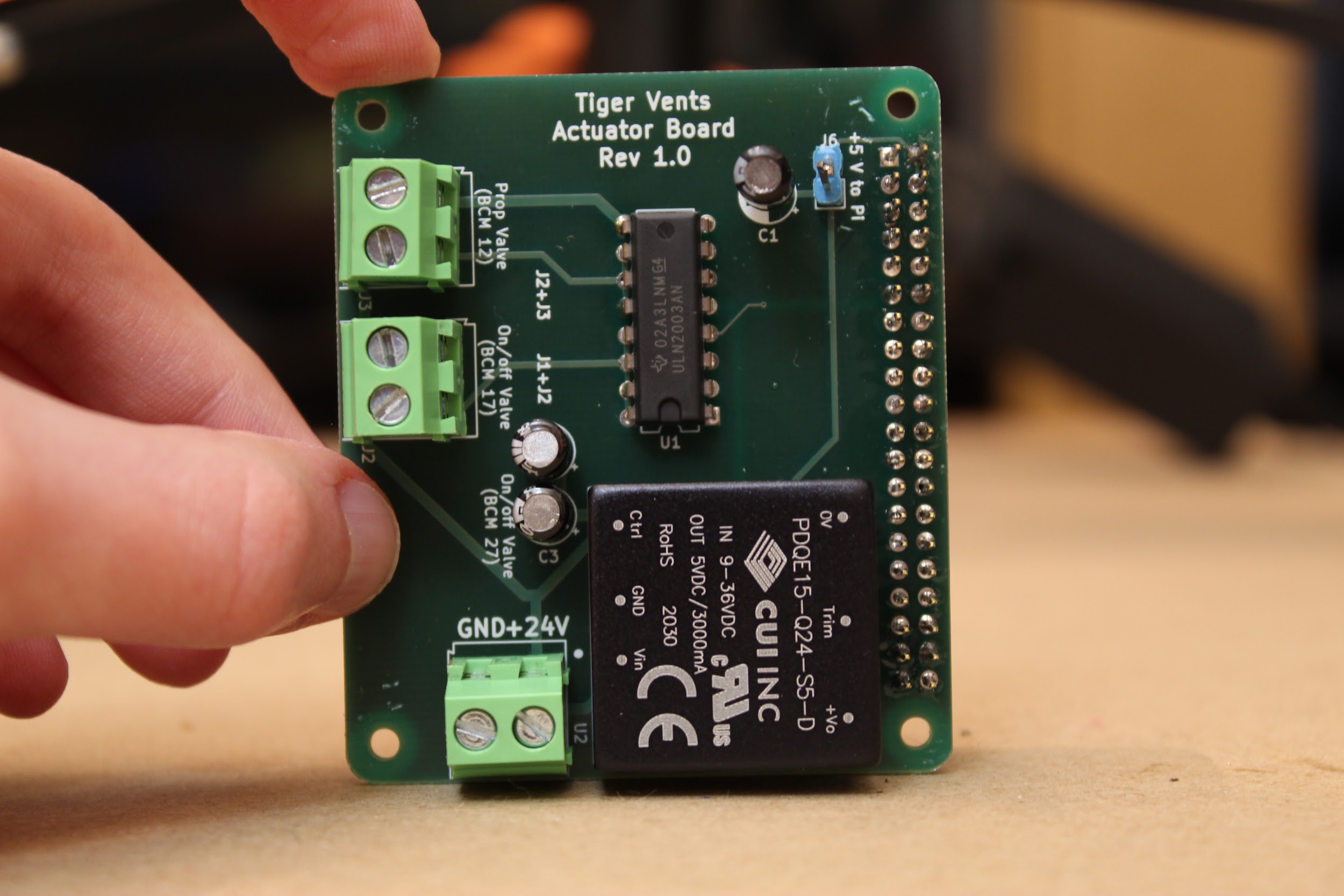
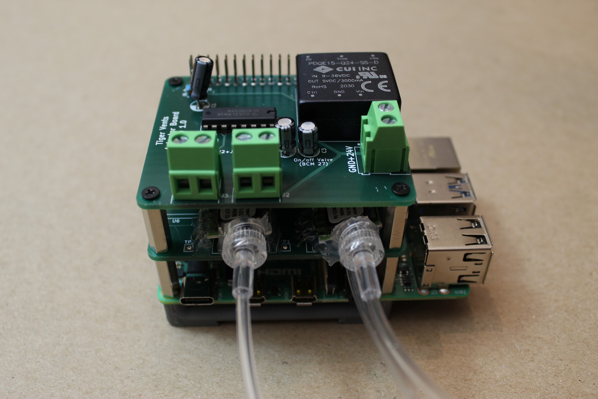
3.2 Assembling the Actuator Board
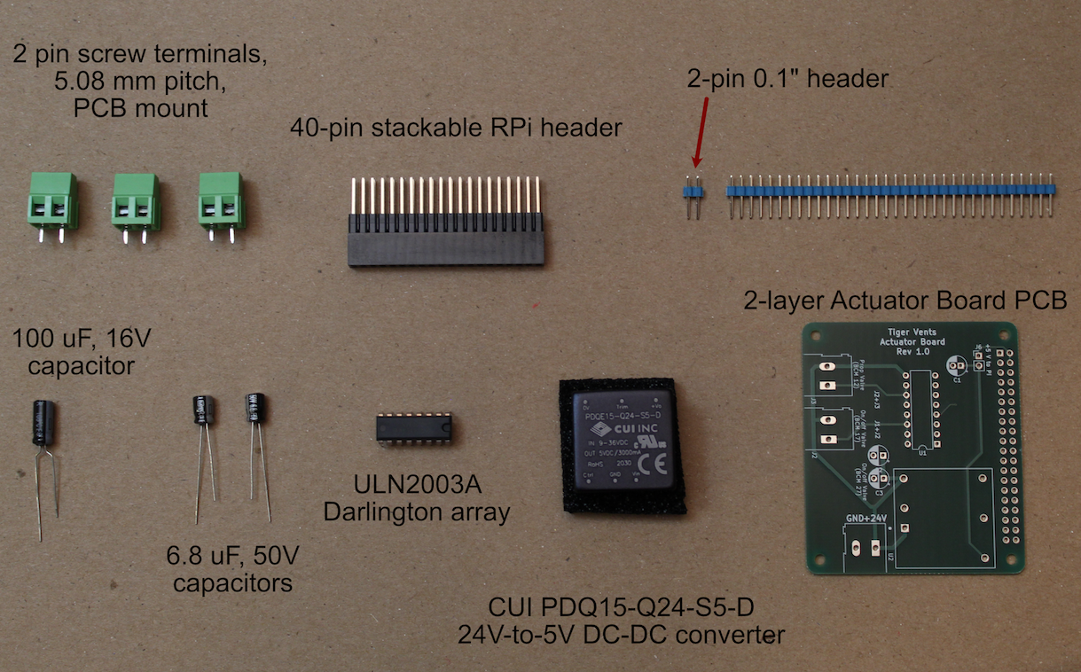
[Image of all components laid out in order/piles, with labels]
You will also need:
A soldering iron
Solder
Helping hands for holding parts while soldering
Wire cutters (for clipping off long capacitor legs)
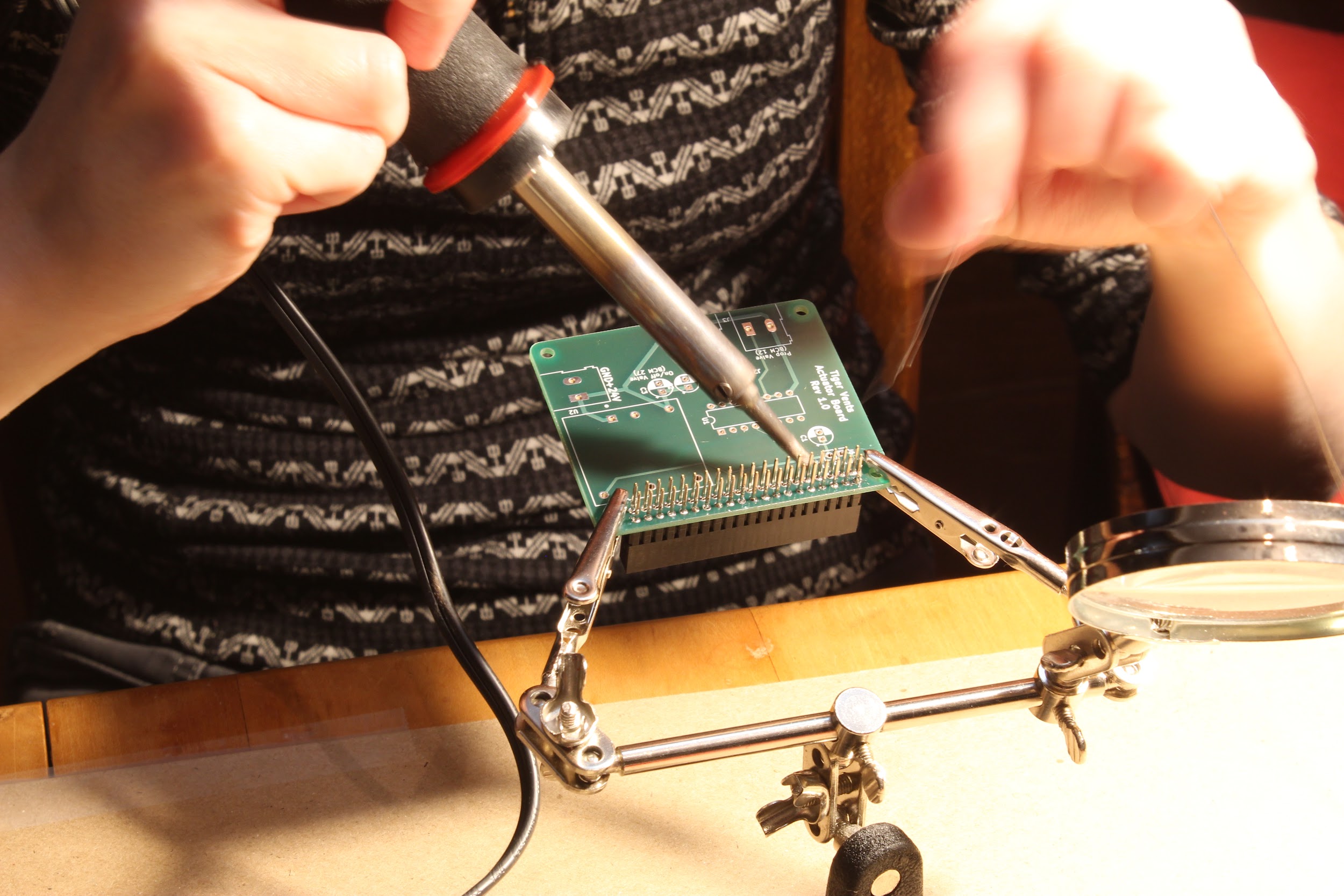
Step 1. Solder the 40-pin stackable RPi header to the Actuator PCB.
Push the pins up from the bottom of the board, as shown, and then solder into place.
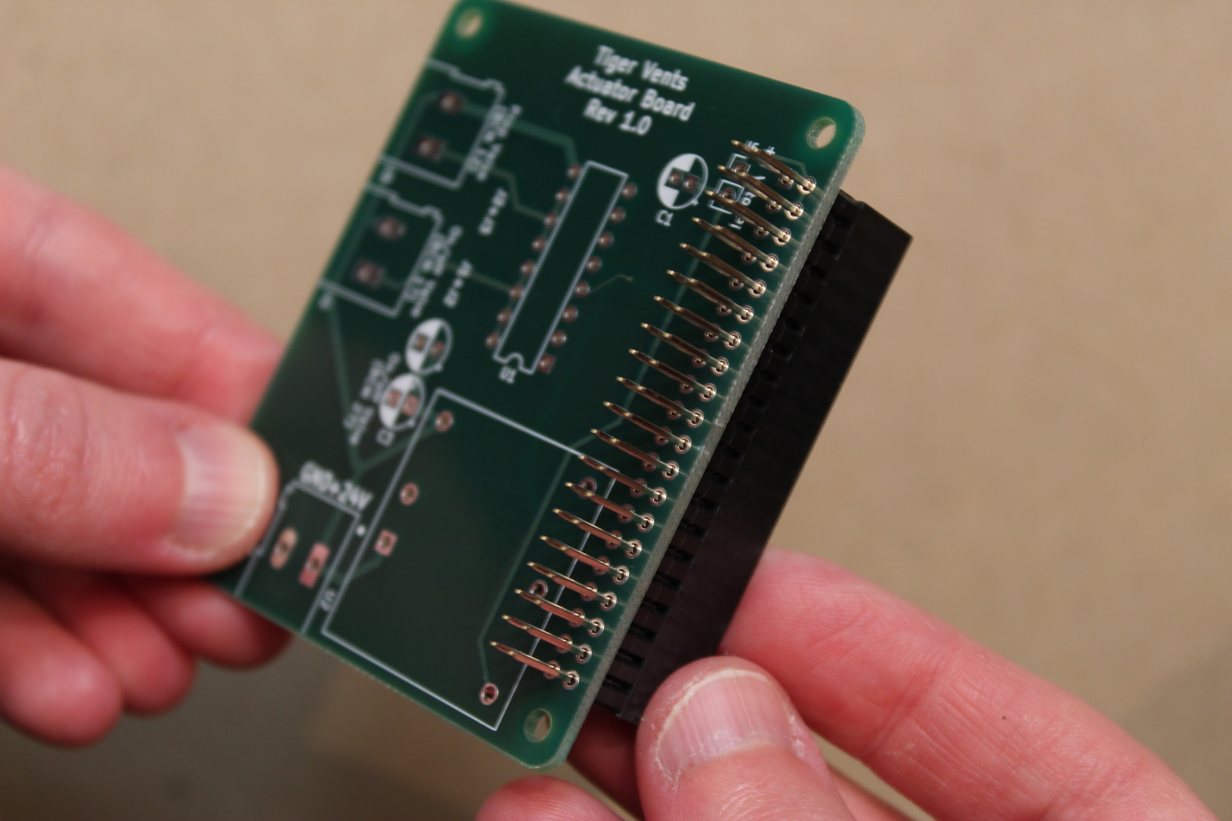
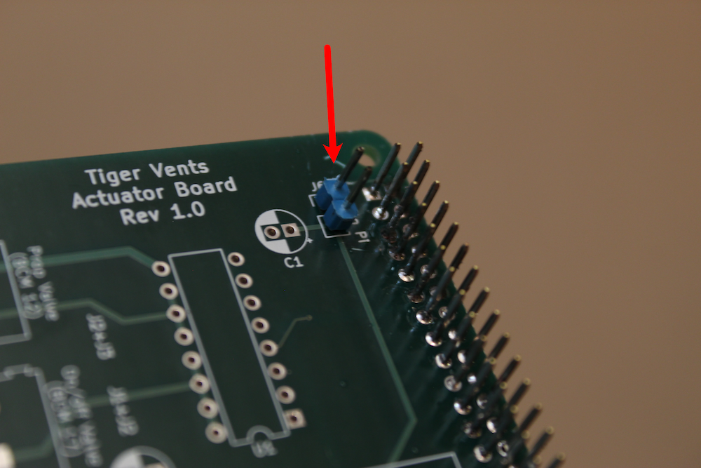
Step 2. Solder the 2-pin 0.1” header onto the board (position J5).
Insert the short end of the pins into the holes from the top of the board, and solder from below. This will leave the long ends of the pins sticking up vertically from the board, as shown:
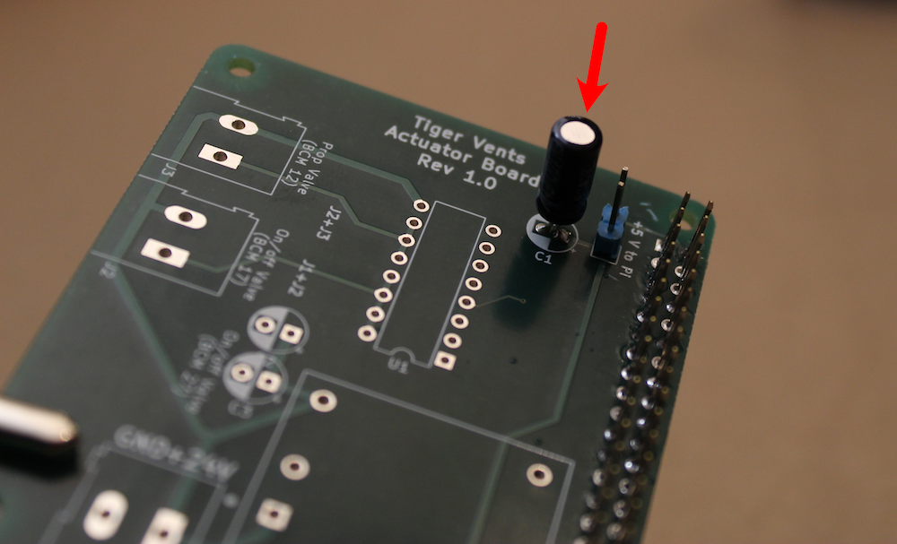
Step 3. Solder the 100 µF, 16V capacitor onto the board (position C1).
Insert the legs of the capacitor into the slots from the top of the board. The longer leg should be inserted into the side marked “+”. Once the capacitor is soldered in place, use wire cutters to clip off the long legs from the back.
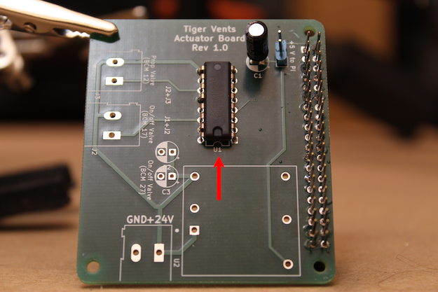
Step 4. Solder the ULN2003A (Darlington array) into place (position U1).
Be sure to match the notched end of the part to the notch indicated on the board.
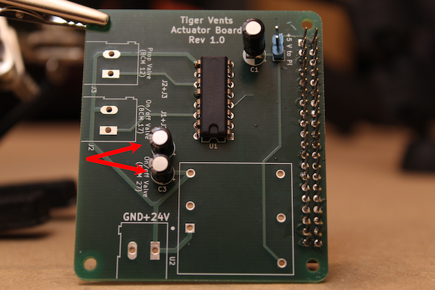
Step 5. Solder the two 6.8 µF, 50V capacitors onto the board (positions C2, C3).
As before, ensure that the longer capacitor legs are inserted through the side marked with the “+”. Once the parts are soldered in, snip the long legs from the back of the board.
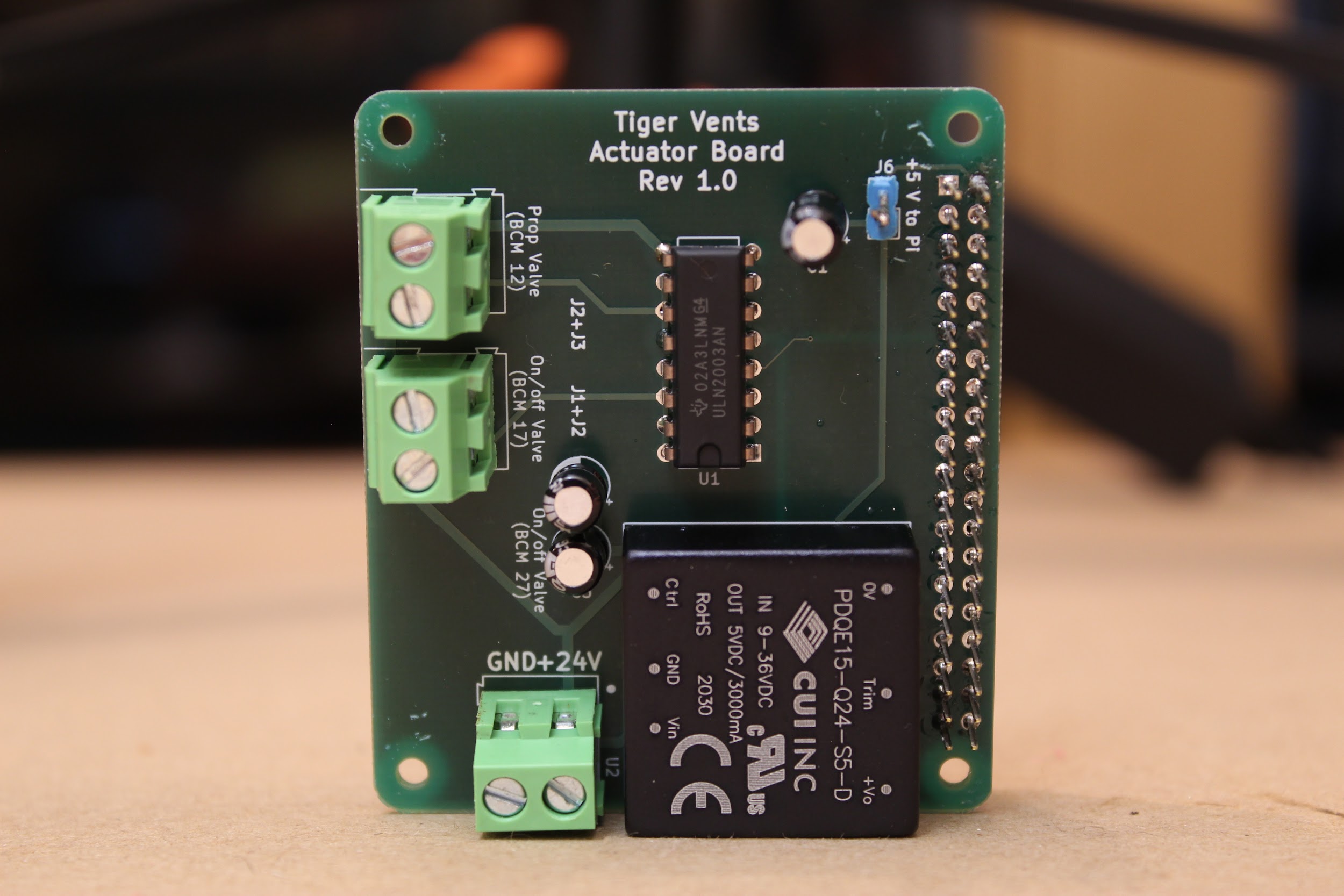
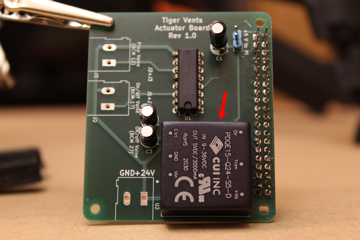
Step 6. Solder the 24-to-5 V DC-DC converter (CUI PDQ15-Q24-S5-D) onto the board, as shown.
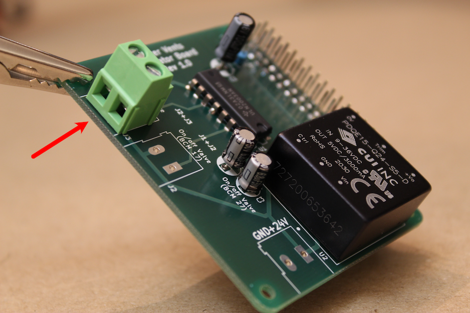
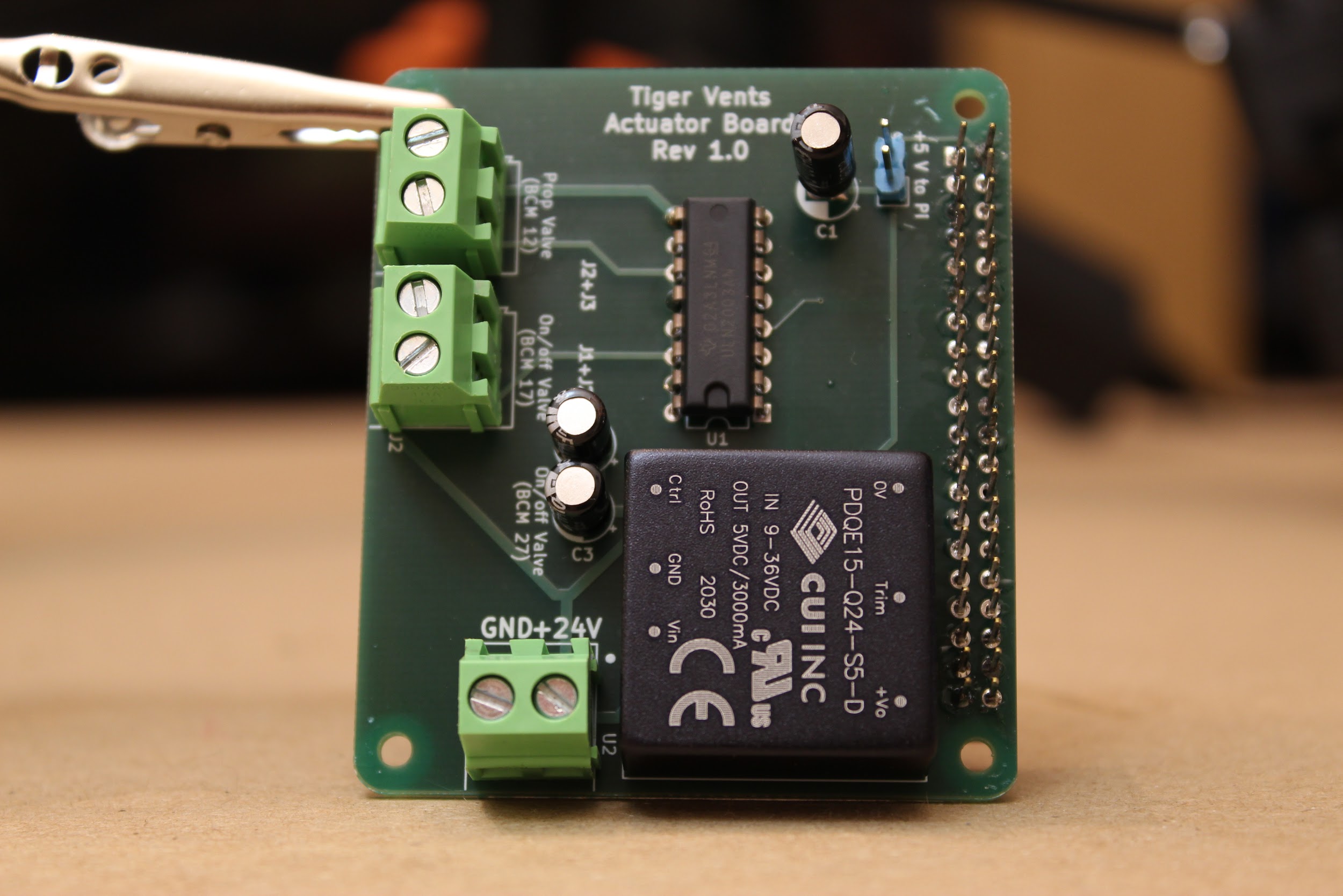
Step 7. Solder the 3 2-pin screw terminals (5.08mm pitch) to the board, as shown.
Be sure to orient all three such that wires can be screwed into the terminals from the outside of the board (as shown).
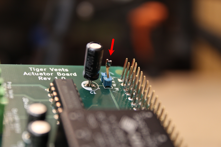
Step 8. Finally, jumper the 2-pin header.
You can use a pin jumper (“shunt”) if you have one, or crush the pins together with a pair of pliers, and then solder the two pins together. We display the latter method, below:
Step 9. The actuator board is ready to go!
3.3 Assembling the PCB-RPi stack
Step 1. Attach three gas sampling lines to the port on the two pressure sensors.
The differential pressure sensor has two ports. If you have an airway-safe glue, feel free to glue these in place (not required).
Step 2. Begin stacking the board by attaching the DIN rail mounts.
You can pre-“tap” the 3D printed DIN rail mounts using the small screws that come with the Raspberry Pi. Then, screw four of the 16mm standoffs through the Raspberry Pi from above, and into the DIN rail mounts, as shown.
Step 3. Next, add the sensor board.
Connect the sensor board via the stackable headers, then use another four 16mm standoffs to attach the board by screwing these into the original four standoffs, using pliers as needed.
Step 4. Add the actuator board.
Connect the actuator board via the stackable headers, then use the four screws that came with your Raspberry Pi to attach the board, as shown.
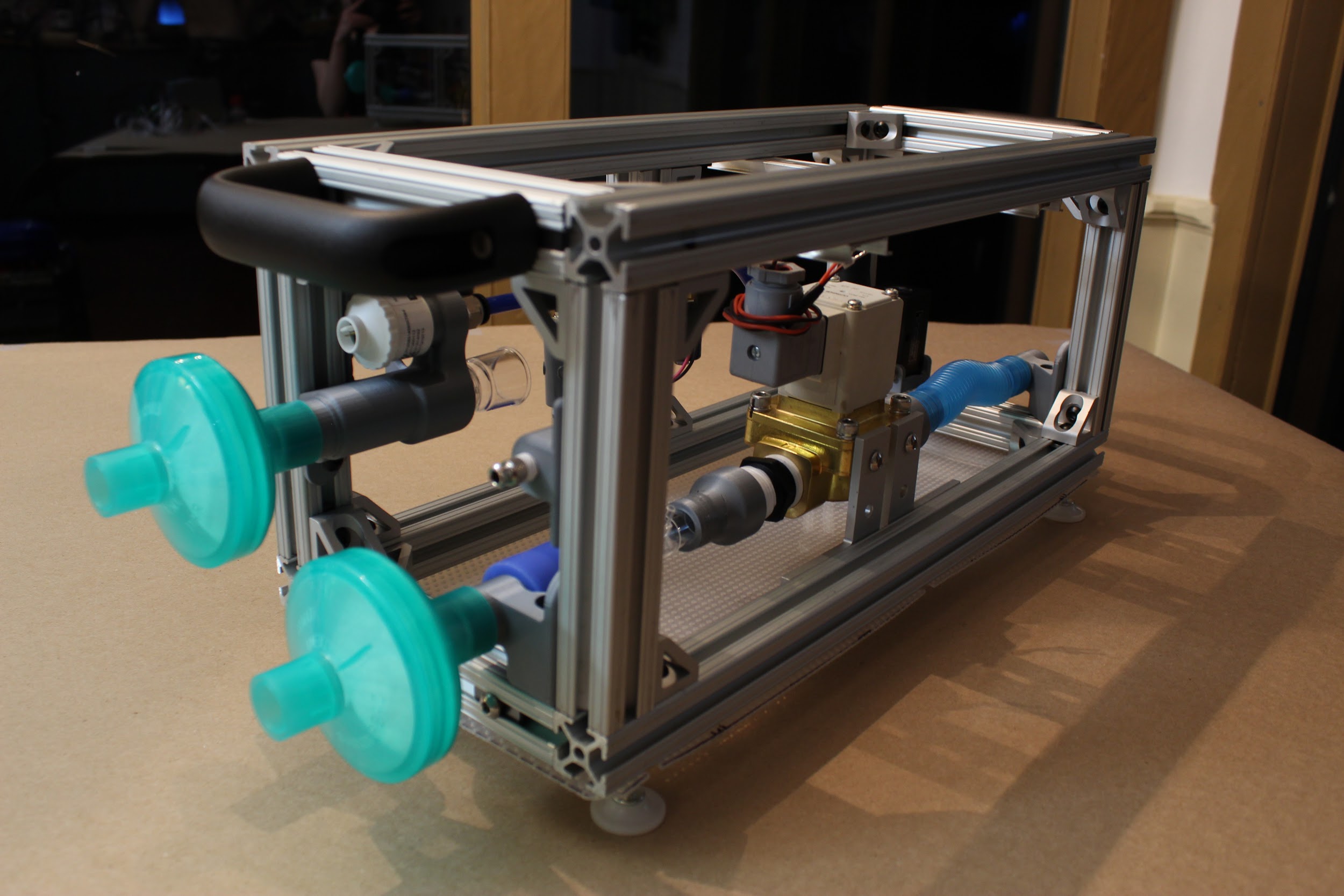
Part 4. Putting it all together
4.1 Wrapping it up.
(Optional step: Attach the side panels using the shorter 80/20 hex screws, as you go.)
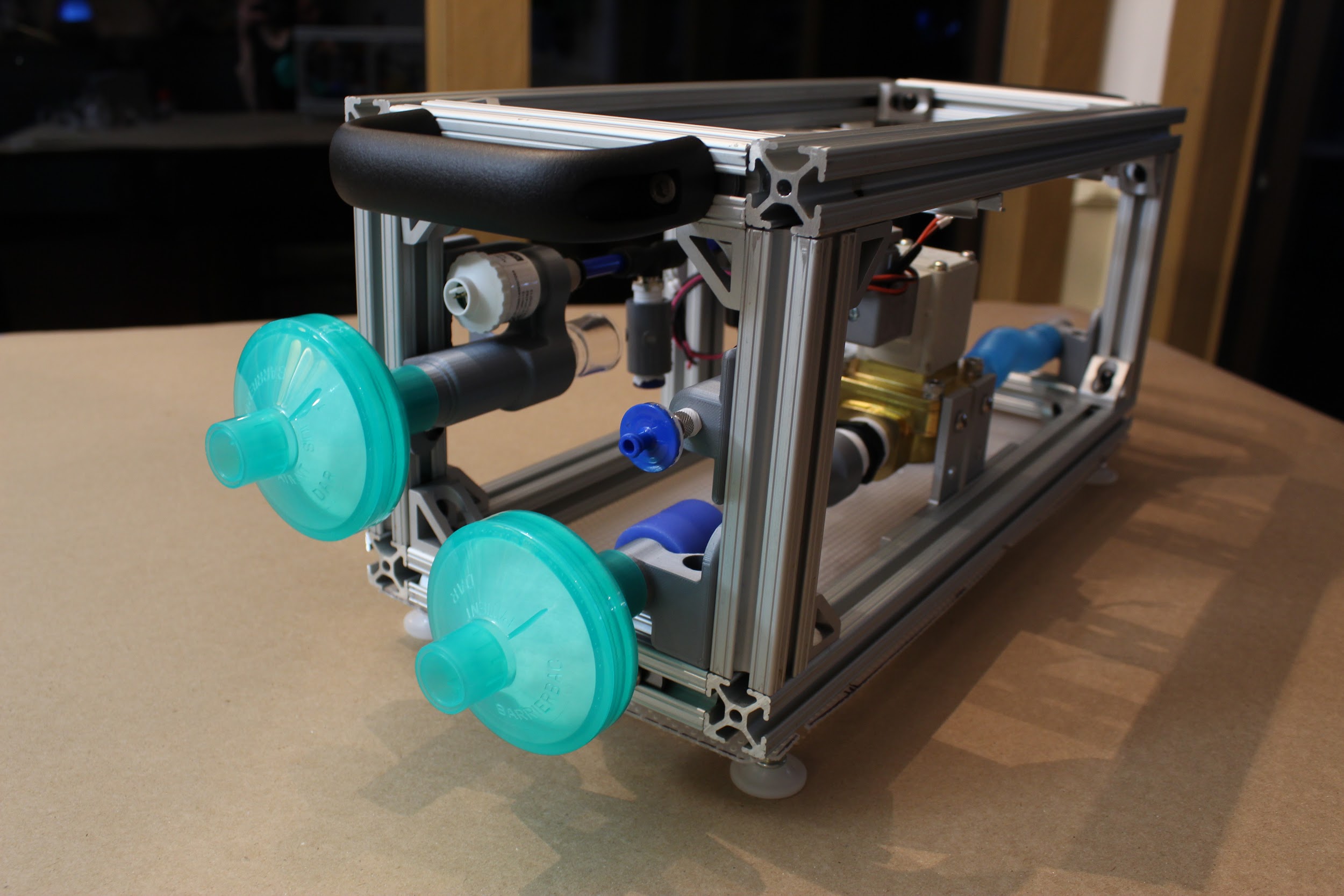
Step 1. Attach the DAR filters.
Insert these by hand to the appropriate ports on the front of the device, as shown: these will attach to the sensor atrium and the expiratory DAR filter bracket. The DAR filters indicate which end should face the patient.
Step 2. Attach the luer lock filter.
This can be twisted on by hand to the luer lock adapter at the front of the device.
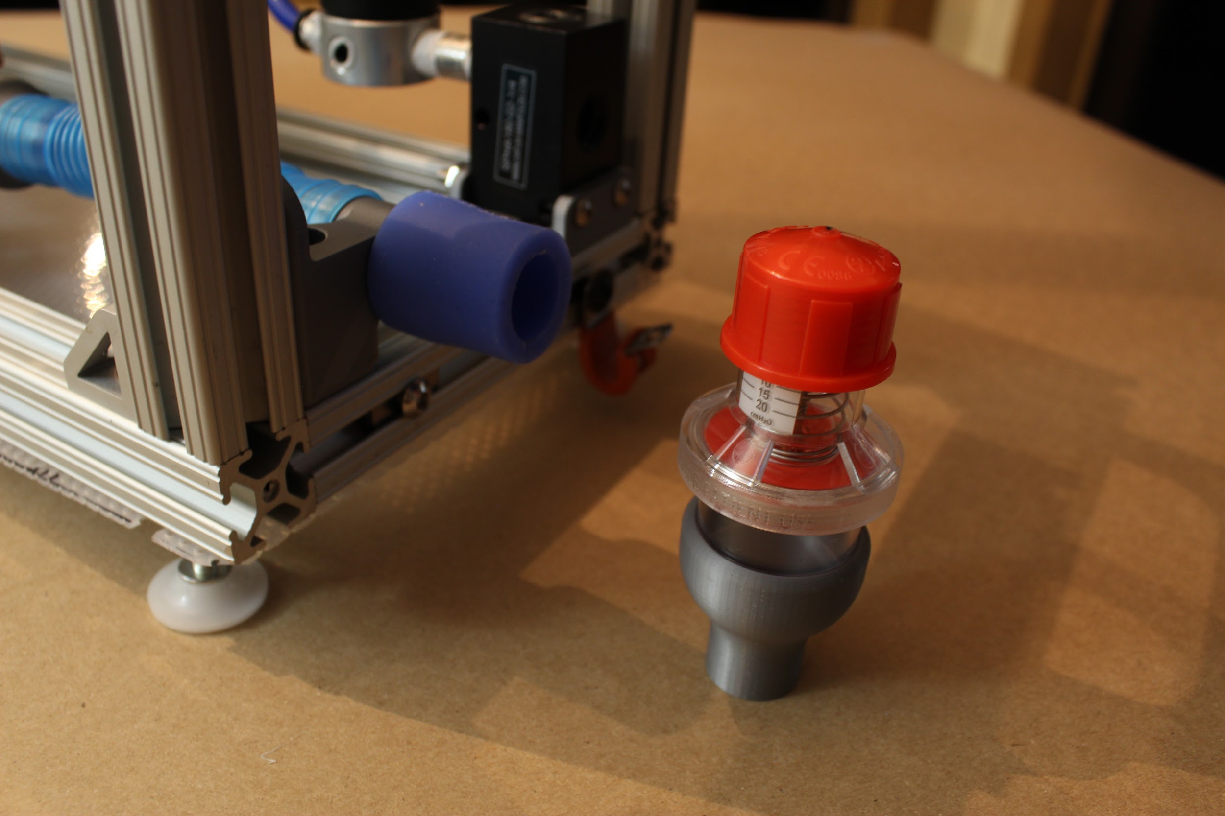
Step 3. Attach the PEEP valve.
If you’re using a commercial PEEP valve, begin by attaching the blue silicone connector. Then, insert the PEEP valve into the 3D printed “22mm to commercial PEEP adapter”- then plug this assembly into the silicone connector.
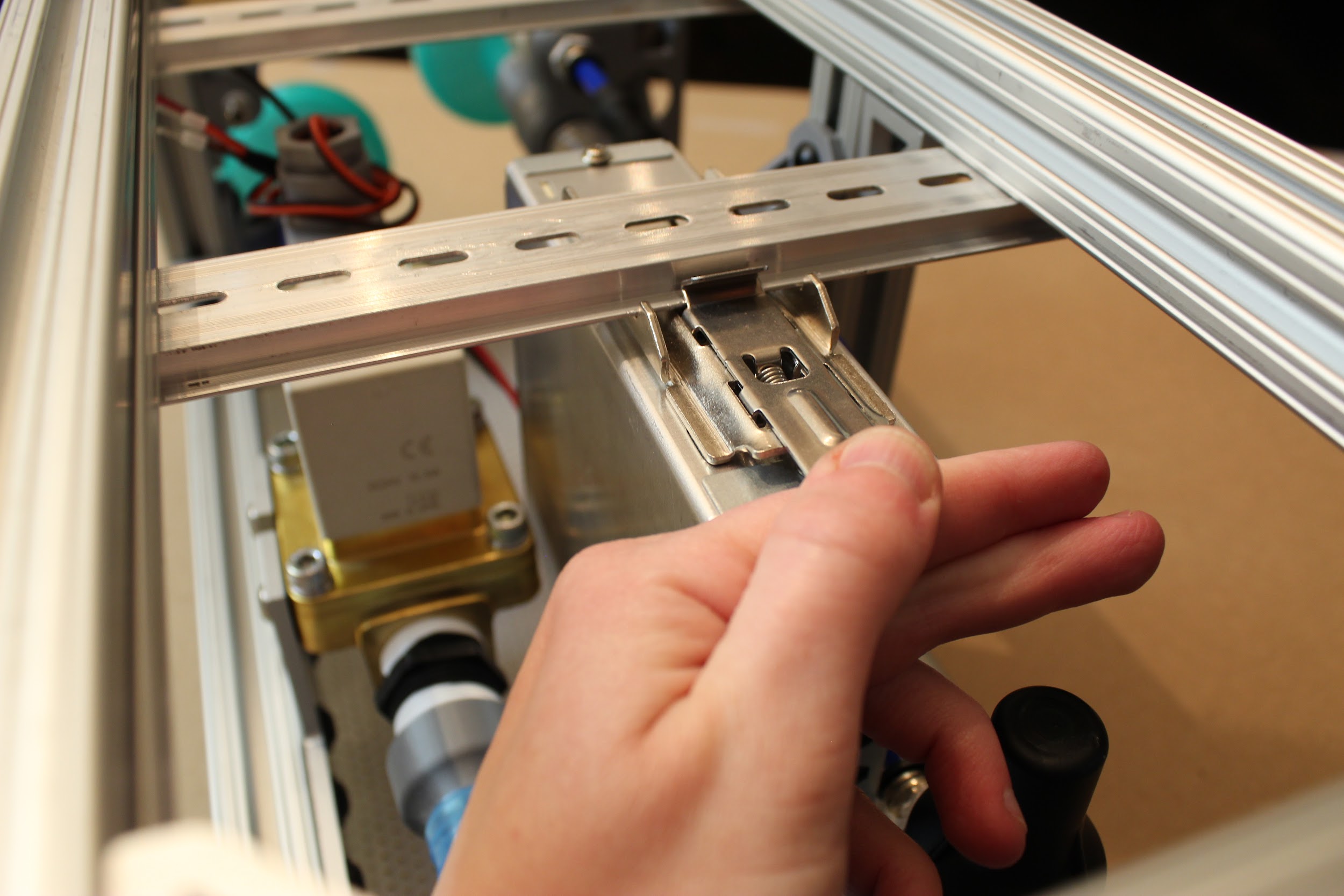
Step 4. Attach the power supply.
Pull the tab on the Meanwell power supply to attach it to the DIN rail closest to the back of the device. It may be necessary to adjust the position of this DIN rail to ensure that the power supply is not touching the expiratory solenoid or inlet manifold/pressure regulator. Feel free to reposition as needed!
*Note: if you wish to attach a rear HPDE panel, we recommend inserting the power cable to the power supply through the grommet of the rear panel before insertion of the power supply into the device. Do this now! You can also attach the “Rear Panel Vent”s to the rear panel; they will snap right in.
Step 5. Attach the luer lock plug to the D-Lite.
The third port on the D-Lite (physically removed from the other two) is not needed; plug that now with a luer lock plug.
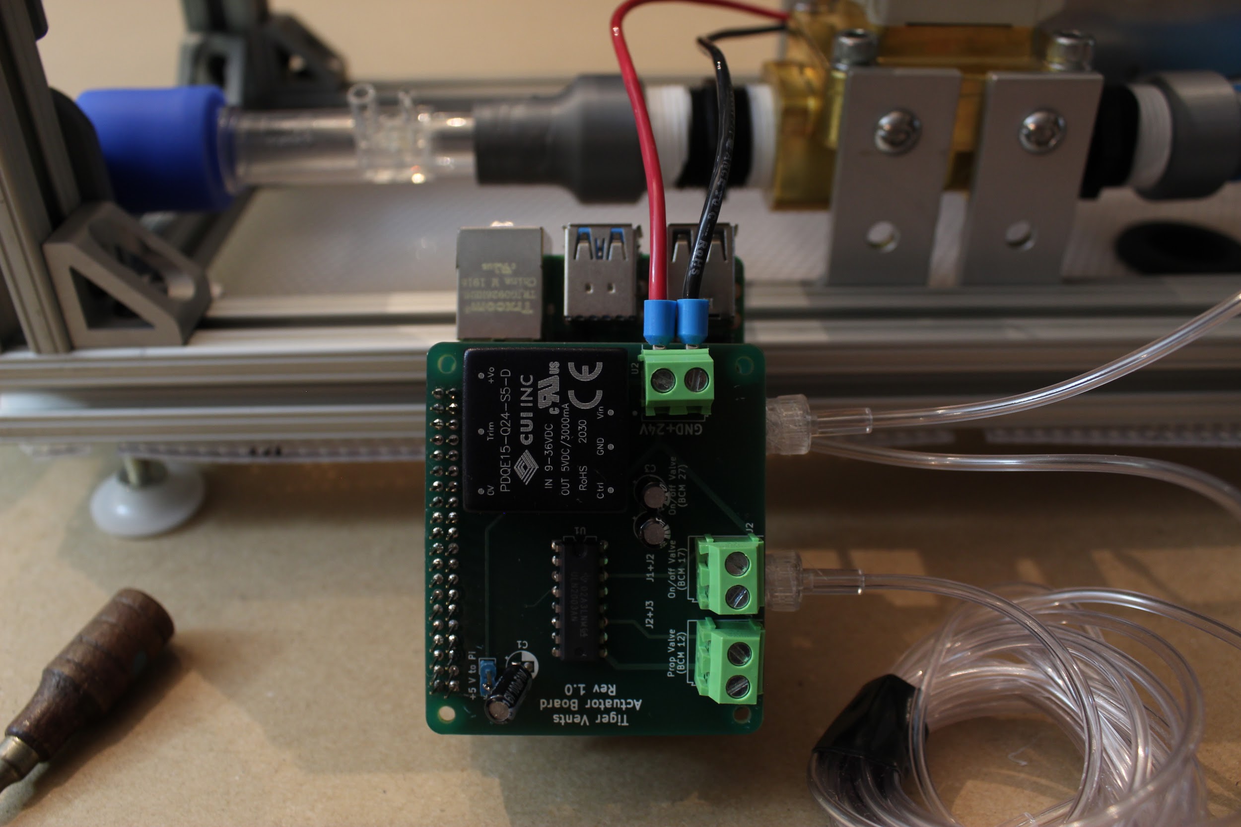
Step 6. Attach the power and ground wires to the PCB stack. Then wire the proportional valve and solenoid.
Use a small flathead screwdriver to attach the power and ground from the power supply to the PCB stack where indicated. Then do the same for the proportional valve wires and the expiratory solenoid wires: the board indicates which pair goes where!
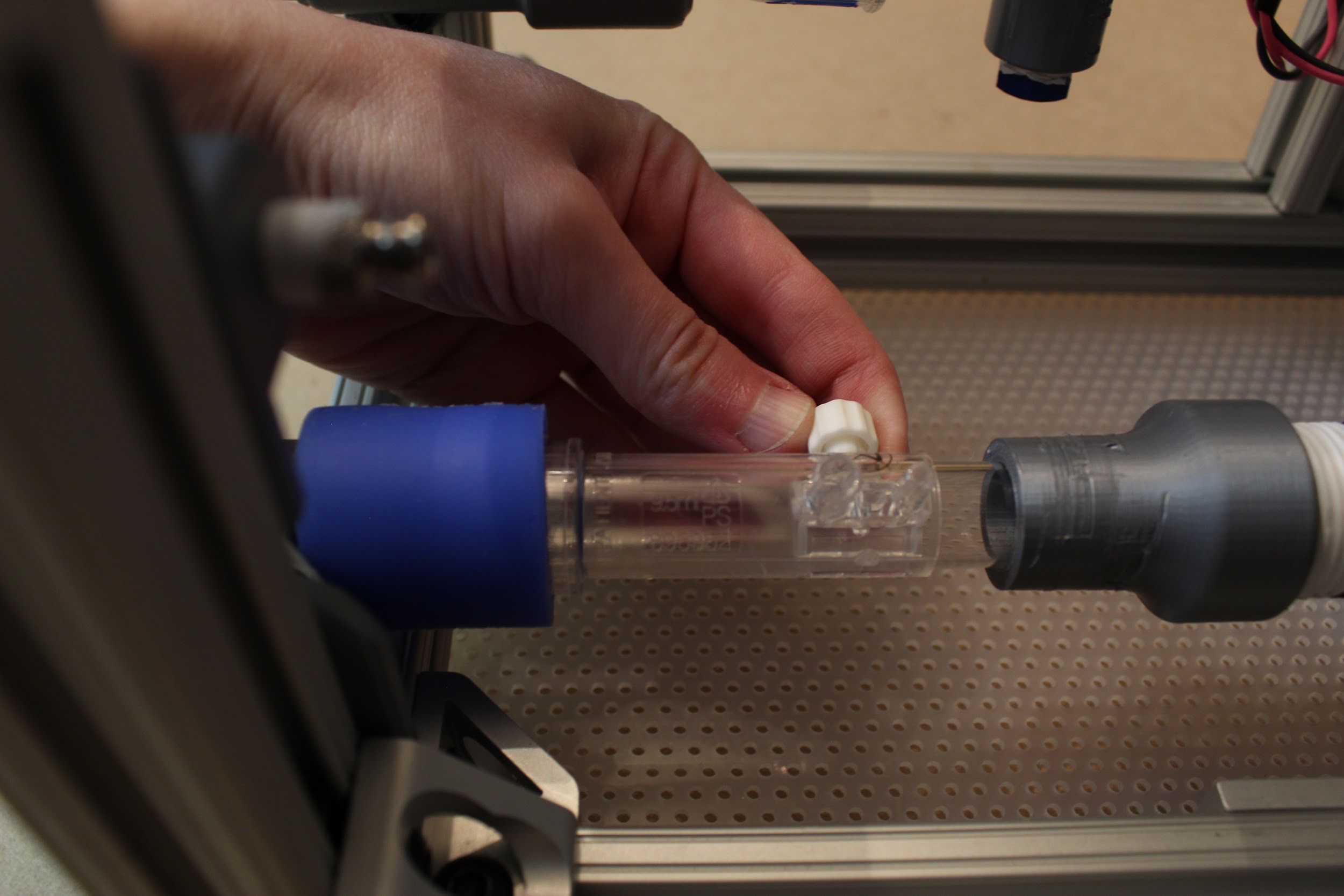
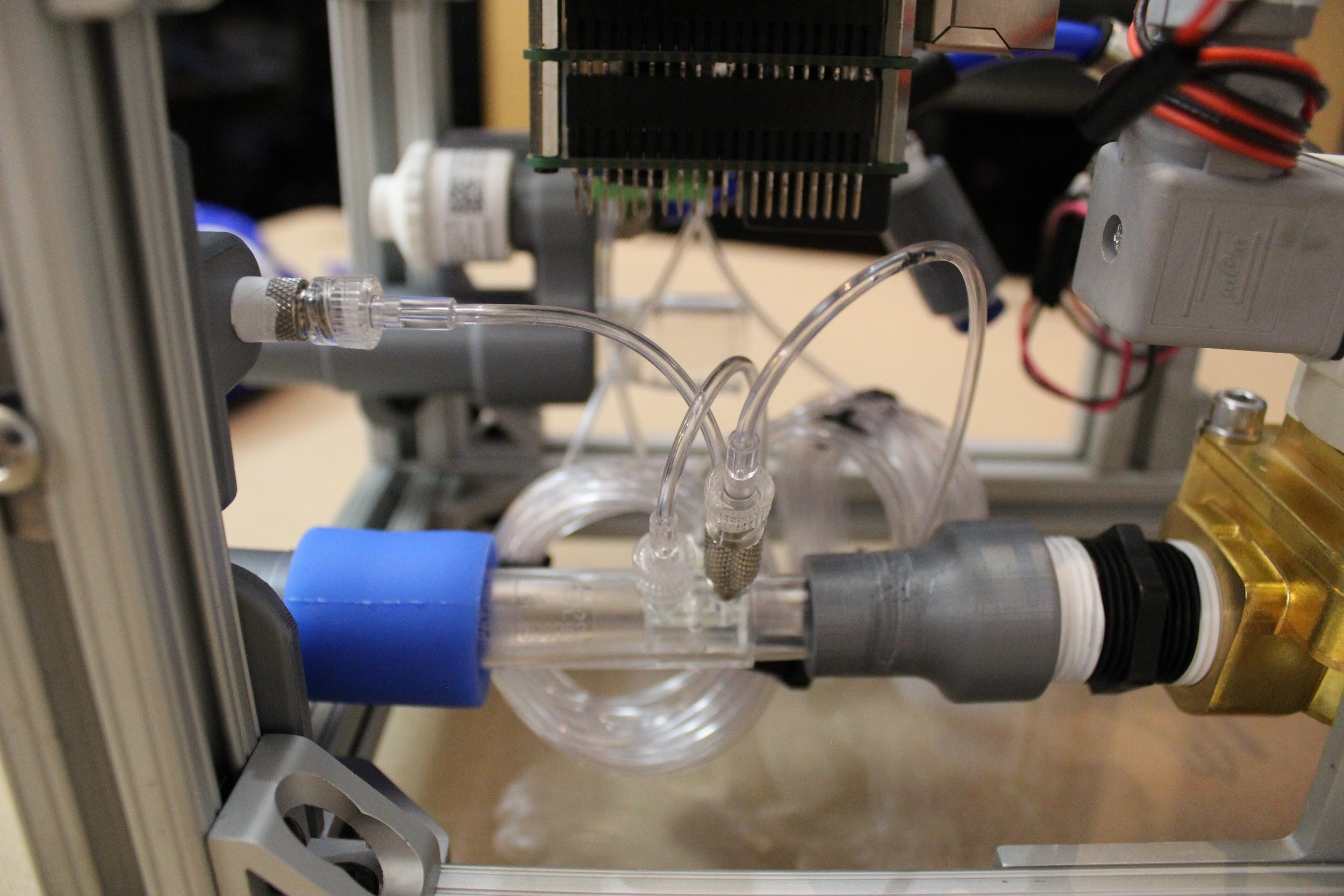
Step 7. Attach the gas sampling lines to the D-Lite.
Use the luer lock connector on the smaller of the two ports, then connect the two gas sampling lines from the differential pressure sensor (from the same sensor on the Sensor Board).
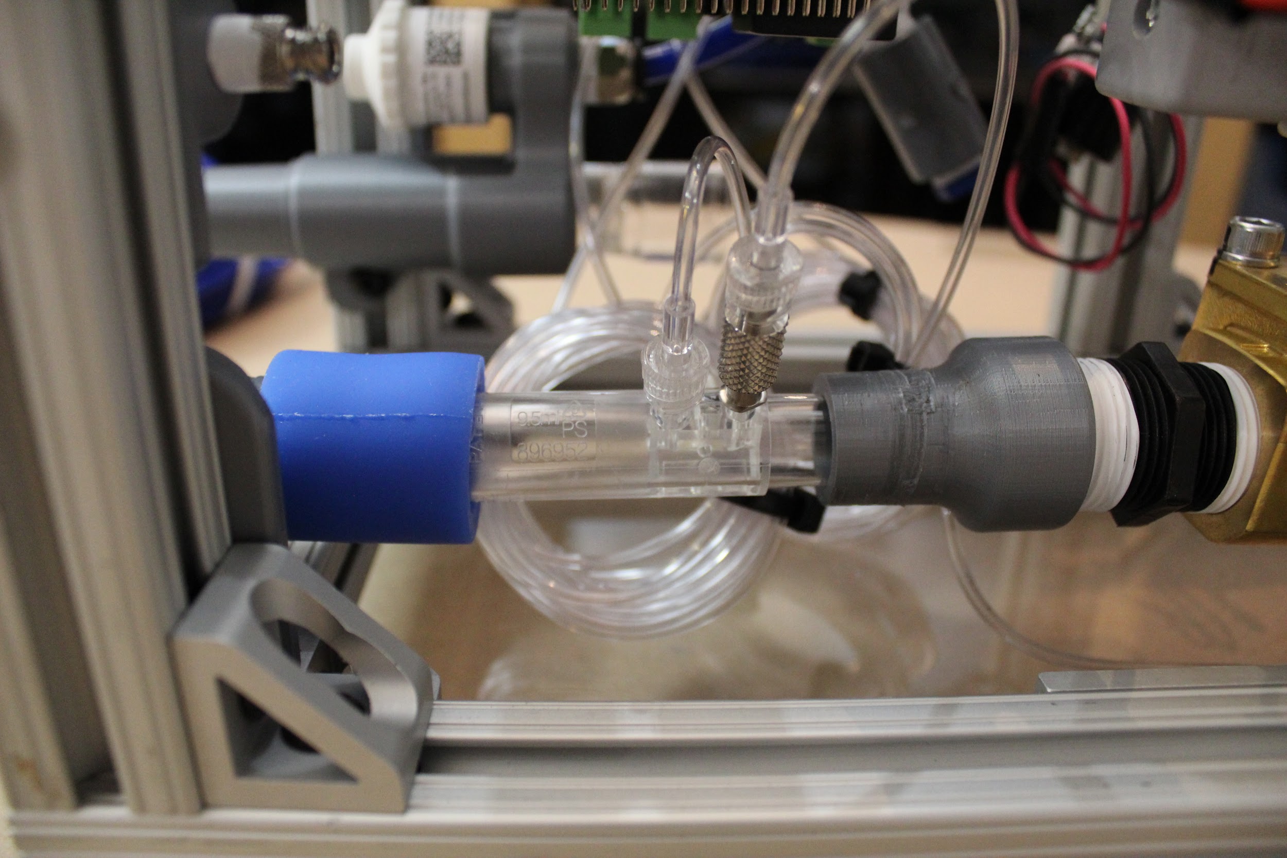
Step 8. Attach the gas sampling line to the luer lock filter mount adapter.
The third gas sampling line runs from the second pressure sensor; attach this to the inner luer lock adapter on the luer lock filter mount.
Step 9. Plug in any required cables to connect the monitor and keyboard.
Run the cables outside of the box through the rubber grommets; wire ties can assist with cable management.
Congratulations! You’re done!