Electronics
PVP block diagram for main electrical components
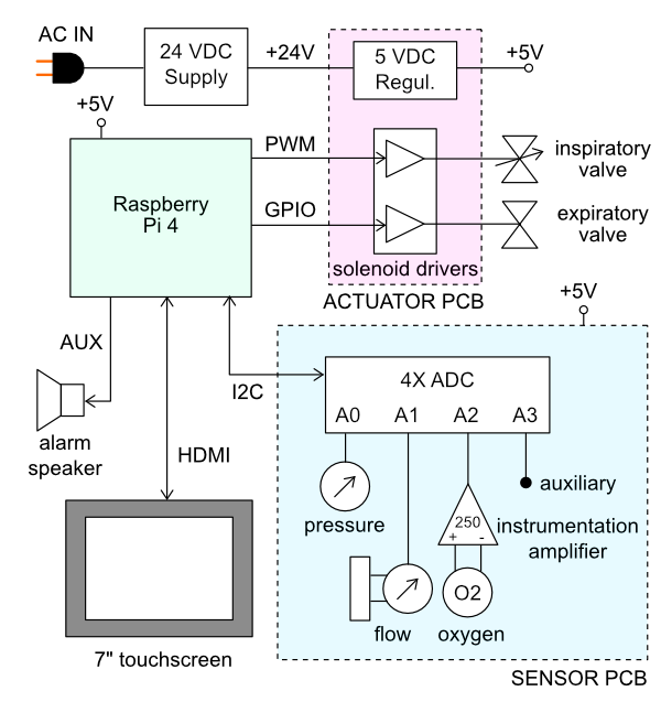
The PVP is coordinated by a Raspberry Pi 4 board, which runs the graphical user interface, administers the alarm system, monitors sensor values, and sends actuation commands to the valves. The core electrical system consists of two modular PCB ‘hats’, a sensor PCB and an actuator PCB, that stack onto the Raspberry Pi via 40-pin stackable headers. The modularity of this system enables individual boards to be revised or modified to adapt to component substitutions if required.
Power and I/O
The main power to the systems is supplied by a DIN rail-mounted 150W 24V supply, which drives the inspiratory valve (4W) and expiratory valves (13W). This voltage is converted to 5V by a switched mode PCB-mounted regulated to power the Raspberry Pi and sensors. This power is transmitted across the PCBs through the stacked headers when required.
Part |
Description |
|---|---|
Meanwell 24 V DC Power Supply |
DIN Rail Power Supplies 150W 24V 5A EN55022 Class B |
Raspberry Pi |
Raspberry Pi- Model B-1 (1GB RAM) |
USB-C Charger/cable |
To power the RPi |
Micro SD Card |
SanDisk Ultra 32GB MicroSDHC UHS-I Card with Adapter |
Raspberry Pi Display |
Matrix Orbital: TFT Displays & Accessories 7 in HDMI TFT G Series |
HDMI for Display |
Display cable: HDMI Cables HDMI Cbl Assbly 1M Micro to STD |
Mini USB for Display |
Display cable: USB Cables / IEEE 1394 Cables 3 ft Ext A-B Mini USB Cable |
Screen mount thumb screws |
SCREEN_MOUNT_THUMB_SCREW: Brass Raised Knurled-Head Thumb Screw, 1/4”-20 Thread Size, 1/2” Long |
Cable grommet |
USER_INTERFACE_CABLE_GROMMET: Buna-N Rubber Grommets, for 1-3/8” Hole Diameter and 1/16” Material Thickness, 1” ID, pack of 10 |
Cable P-clip |
USER_INTERFACE_CABLE_P-CLIP_0.375_ID_SS: Snug-Fit Vibration-Damping Loop Clamp, 304 Stainless Steel with Silicone Rubber Cushion, 3/8” ID, pack of 10, 17/64 mounting holes |
Keyboard |
Adesso: Mini keyboard with trackball |
Sensor PCB
The sensor board interfaces four analog output sensors with the Raspberry Pi via I2C commands to a 12-bit 4-channel ADC (Adafruit ADS1015).
an airway pressure sensor (Amphenol 1 PSI-D-4V-MINI)
a differential pressure sensor (Amphenol 5 INCH-D2-P4V-MINI) to report the expiratory flow rate through a D-Lite spirometer
an oxygen sensor (Sensiron SS-12A) whose 13 mV differential output signal is amplified 250-fold by an instrumentation amplifier (Texas Instruments INA126)
a fourth auxiliary slot for an additional analog output sensor (unused)
A set of additional header pins allows for digital output sensors (such as the Sensiron SFM3300 flow sensor) to be interfaced with the Pi directly via I2C if desired.
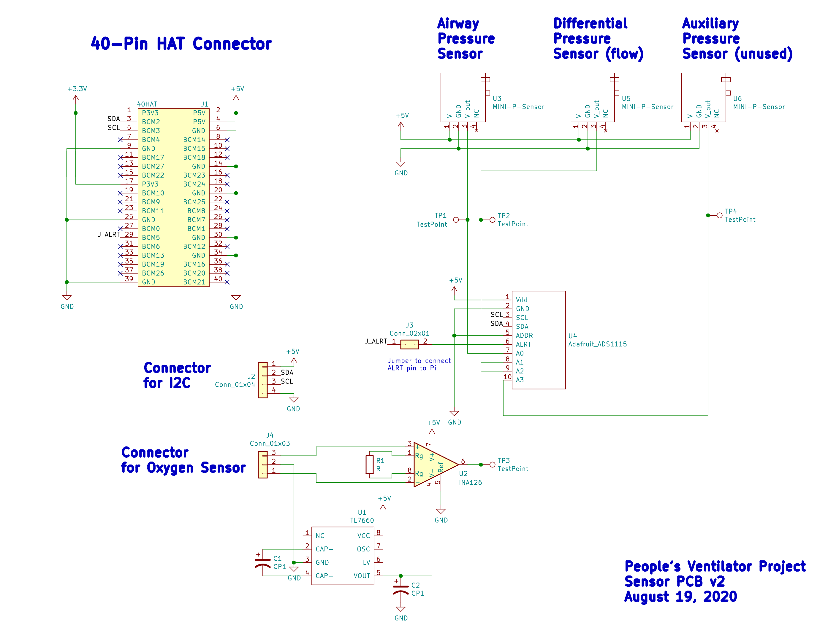
Sensor PCB schematic
Ref |
Part |
Purpose |
|---|---|---|
J1 |
40-pin stackable RPi header |
Connects board to RPi |
J2 |
4-pin 0.1” header |
I2C connector if desired |
J3 |
2-pin 0.1” header |
Connects ALRT pin from ADS1115 to RPi if needed |
J4 |
3-pin 0.1” header or 3 pin fan extension cable |
Connects board to oxygen sensor |
R1 |
330 Ohm resistor |
Sets gain for INA126 |
C1 |
10 uF, 25V |
Cap for TL7660 |
C2 |
10 uF, 25V |
Cap for TL7660 |
U1 |
TL7660, DIP8 |
Rail splitter for INA126 |
U2 |
INA126, DIP8 |
Instrumentation amplifier for oxygen sensor output |
U3 |
Amphenol 5 INCH-D2-P4V-MINI |
Differential pressure sensor (for flow measurement) |
U4 |
Adafruit ADS1115 |
4x 12-bit ADC |
U5 |
Amphenol 1 PSI-D-4V-MINI |
Airway pressure sensor |
U6 |
Auxiliary analog output sensor slot |
Actuator PCB
The purpose of the actuator board is twofold:
regulate the 24V power supply to 5V (CUI Inc PDQE15-Q24-S5-D DC-DC converter)
interface the Raspberry Pi with the inspiratory and expiratory valves through an array of solenoid drivers (ULN2003A Darlington transistor array)
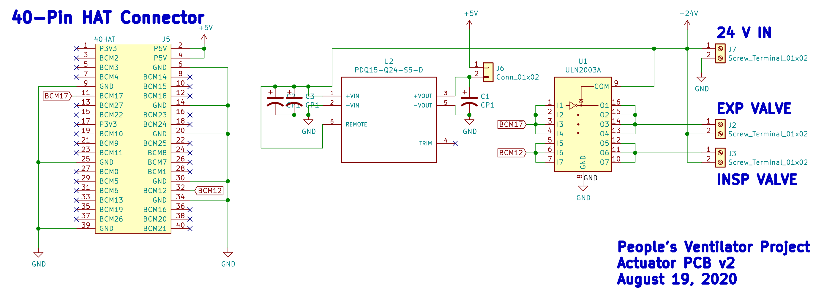
Actuator PCB schematic
Ref |
Part |
Purpose |
|---|---|---|
J2 |
2-pin screw terminal, 5.08 mm pitch, PCB mount |
Connects to 24V supply |
J3 |
2-pin screw terminal, 5.08 mm pitch, PCB mount |
Connects to on/off expiratory valve |
J4 |
2-pin screw terminal, 5.08 mm pitch, PCB mount |
Connects to inspiratory valve, driven by PWM |
J5 |
40-pin stackable RPi header |
Connects board to RPi |
J6 |
2-pin 0.1” header |
Jumper between 5V and Raspberry Pi |
C1 |
100 uF, 16V |
5V rail filter cap |
C2 |
6.8 uF, 50V |
24V rail filter cap |
C3 |
6.8 uF, 50V |
24V rail filter cap |
U1 |
ULN2003A |
Darlington BJT array to drive solenoids |
U2 |
CUI PDQ15-Q24-S5-D |
24-to-5V DC-DC converter |